Need Full Specifications?
Download our 2025 Product Catalog for detailed drawings and technical parameters of all switchgear components.
Get CatalogDownload our 2025 Product Catalog for detailed drawings and technical parameters of all switchgear components.
Get CatalogDownload our 2025 Product Catalog for detailed drawings and technical parameters of all switchgear components.
Get Catalog
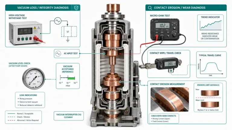
A vacuum contactor’s interrupting chamber maintains internal pressure below 10⁻³ Pa to achieve the dielectric strength necessary for reliable arc extinction. When this vacuum degrades—through slow leakage or contact erosion—the contactor loses its ability to safely interrupt load currents. Detecting vacuum bottle leaks before failure occurs is the central challenge for maintenance teams working with medium-voltage motor control and capacitor switching applications.
Vacuum degradation follows two primary pathways: mechanical seal failure and metallurgical breakdown.
Mechanical leaks typically occur at ceramic-to-metal brazed joints. Thermal cycling induces micro-cracks in these hermetic seals, which must withstand temperature differentials of 80–120°C during normal switching duty while maintaining leak rates below 10⁻¹⁰ Pa·m³/s throughout the device’s operational life. In field assessments across industrial motor control applications, these seal failures account for the majority of premature vacuum loss.
The second mechanism involves contact material consumption. Contactor-grade vacuum bottles use CuCr or AgWC (silver-tungsten carbide) contact compositions optimized for the 200–600 A current range. Each switching operation erodes approximately 0.1–0.5 μg of contact material, depositing metallic vapor condensate on internal chamber surfaces. This erosion accumulates over hundreds of thousands of operations.
The relationship between vacuum pressure and dielectric capability follows Paschen’s law. At pressures above 10⁻¹ Pa, the mean free path of gas molecules shortens enough to support sustained ionization, reducing breakdown voltage from greater than 30 kV to potentially below the contactor’s rated voltage. This threshold marks the boundary between serviceable and failed vacuum interrupter assemblies.
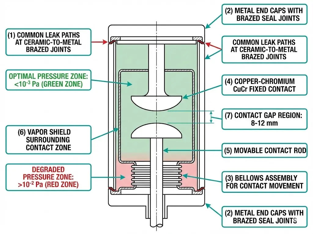
Systematic field testing identifies vacuum degradation before catastrophic failure. When vacuum pressure rises above 10⁻² Pa, the dielectric strength drops dramatically, compromising both arc quenching capability and personnel safety.
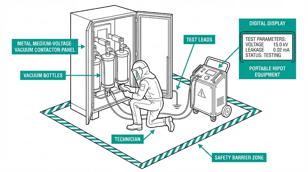
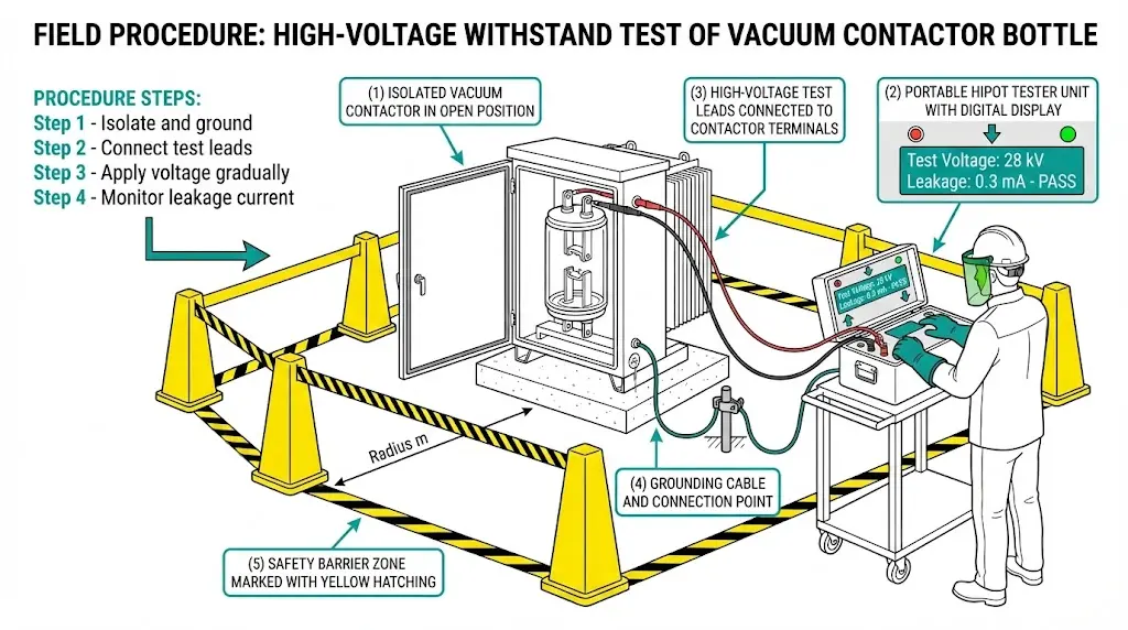
The most accessible field method is AC or DC withstand testing. For a 12 kV vacuum contactor, test voltage of approximately 28–32 kV is applied across open contacts for one minute.
Field procedure:
This method detects gross vacuum loss effectively but has limitations. Partial degradation (pressure at 10⁻¹ Pa) may pass withstand testing yet fail under actual fault conditions where arc extinction depends critically on vacuum quality.
MAC testing detects vacuum degradation by measuring X-ray emission when contacts separate under voltage. In properly evacuated bottles (pressure < 10⁻³ Pa), minimal ionization occurs. As pressure increases, X-ray intensity rises proportionally.
Field units typically operate at 10–20 kV DC with sensitivity to detect degradation at 10⁻¹ Pa—well before functional failure. However, MAC testers require specialized training and equipment investment that limits their availability for routine maintenance.
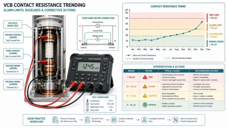
Contact resistance trending provides indirect end-of-life indication. New CuCr contacts typically show resistance below 50 μΩ per pole. In applications with frequent switching exceeding 100,000 operations, resistance values climbing to 150–200 μΩ indicate significant erosion requiring replacement.
This method doesn’t measure vacuum directly but flags conditions that often accompany seal degradation.
[Expert Insight: Field Testing Realities]
- Environmental factors significantly affect accuracy: humidity above 70% and temperature fluctuations greater than ±15°C compromise high-voltage test reliability
- A single “pass” result provides point-in-time confidence only—not long-term assurance
- Combine multiple methods when possible: hipot + contact resistance + operation counting yields better predictive value than any single test
- Document baseline values at commissioning; trending data proves more valuable than absolute thresholds
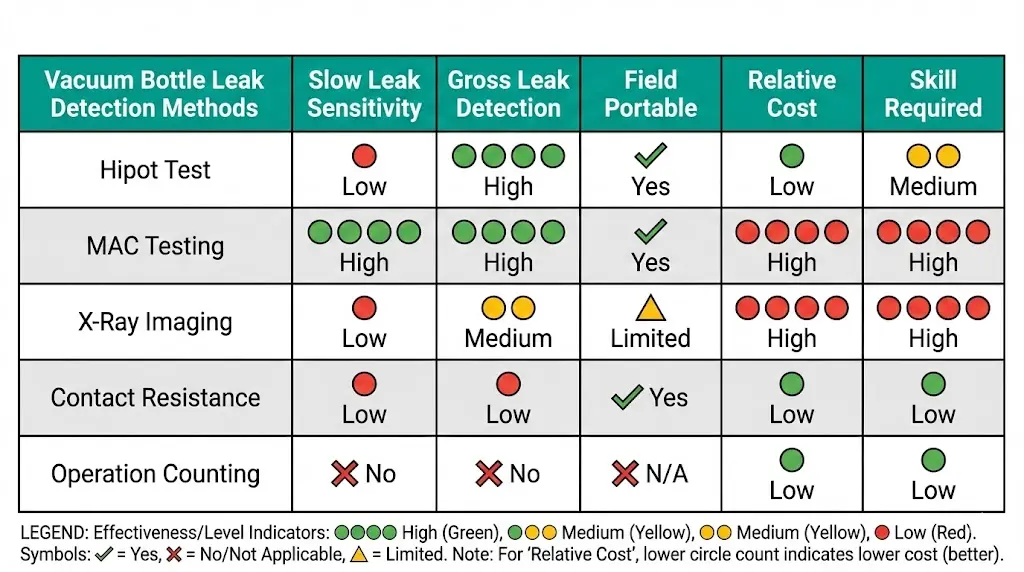
No single field method guarantees detection of incipient leaks. Each technique offers specific advantages and limitations that maintenance teams must weigh against available resources and consequence of failure.
| Detection Method | Slow Leak Detection | Gross Leak Detection | Field Portable | Relative Cost | Skill Level |
|---|---|---|---|---|---|
| AC/DC Hipot | Low | High | Yes | Low–Medium | Medium |
| MAC Testing | Medium–High | High | Limited | High | High |
| X-Ray Imaging | High | High | No | Very High | Specialized |
| Contact Resistance | Indirect only | Indirect only | Yes | Low | Low |
| Operation Counting | Predictive | Predictive | Yes | Minimal | Low |
For routine maintenance programs, the practical combination is hipot testing plus contact resistance measurement plus operation tracking. This triad catches most failure modes at reasonable cost. Reserve MAC or X-ray methods for critical applications where unplanned outage carries severe consequences—continuous process plants, hospital essential power, or high-value production lines.
The key insight from field experience: vacuum bottle assessment works best as trend analysis rather than pass/fail determination. A bottle showing 15% withstand voltage decline over two years warrants closer attention than one maintaining stable readings, even if both currently exceed minimum thresholds.
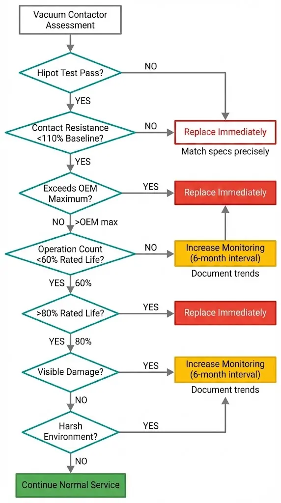
Translating test results into maintenance decisions requires clear criteria. The following framework applies to medium-voltage vacuum contactors in industrial service.
All conditions must be met:
Any of these conditions triggers closer observation:
Any single condition warrants replacement:
Vacuum bottles are factory-sealed and non-refurbishable. Field replacement means swapping the entire vacuum interrupter assembly. Match stroke length, contact gap, and rated voltage/current to original specifications precisely.
Lead times from vacuum contactor manufacturers typically run 8–16 weeks. Stock spare assemblies for critical applications where unplanned outage carries high consequence.
Honest acknowledgment of testing limitations builds trust and prevents overconfidence in diagnostic results.
Micro-cracks can propagate after testing. A vacuum bottle that passes all field tests today may fail within months if a seal defect worsens under continued thermal cycling. All field tests provide point-in-time snapshots, not predictive warranties.
Slow leak rates at 10⁻⁴ Pa/year may not manifest detectable symptoms for years after initial testing. By the time degradation becomes measurable through standard methods, the bottle may already be approaching the critical 10⁻² Pa threshold.
Contact gap, bellows design, ceramic composition, and vapor shield geometry differ significantly between manufacturers. Generic test thresholds may not apply universally. Always reference OEM technical bulletins for specific models.
Some manufacturers offer factory re-test services for removed bottles—a valuable option for critical applications where confirmation justifies logistics cost.
IEC 62271-106 defines vacuum contactor requirements but does not mandate specific field leak detection procedures. IEEE C37.85 covers vacuum switching device test methods but focuses primarily on laboratory conditions. Field practitioners often rely on manufacturer guidance combined with industry working group publications from CIGRE and IEEE PES.
[Expert Insight: What Standards Don’t Tell You]
- IEC endurance ratings assume laboratory conditions—field installations with temperature swings, vibration, or contamination may reach end-of-life earlier
- Approximately 12% of vacuum contactor failures in industrial service stem from vacuum loss rather than mechanical wear
- The 10⁻² Pa pressure threshold is conservative; functional degradation often begins at 10⁻¹ Pa under high-current switching
- Document everything—a rising trend curve predicts failure more reliably than any single absolute measurement
Effective vacuum bottle management combines systematic testing with practical logistics planning.
For applications requiring vacuum circuit breaker or contactor solutions with documented vacuum integrity testing, work with manufacturers who provide factory test certificates and technical support for field assessment programs.
For vacuum circuit breaker and contactor applications, the following thresholds indicate end-of-life conditions requiring immediate replacement:
| Application Type | Recommended Methods | Test Frequency |
|---|---|---|
| General industrial | Hipot + Contact resistance | Annual |
| Critical process | Hipot + MAC + Contact resistance | Semi-annual |
| Safety systems | Full suite including X-ray | Per manufacturer specification |
External Reference: IEC 62271-106 — IEC 62271-106 standard for AC contactors
Q: How do you test a vacuum contactor bottle for leaks in the field?
A: Apply AC or DC hipot voltage across open contacts at 80% of rated withstand level while monitoring leakage current. Values exceeding 1 mA or flashover below threshold voltage indicate vacuum degradation requiring further investigation or replacement.
Q: What causes vacuum loss in contactor bottles over time?
A: Thermal cycling stresses ceramic-to-metal brazed seals, creating micro-cracks that allow slow air ingress. High switching frequency accelerates bellows fatigue, while contact erosion releases metal particles that can compromise internal surfaces.
Q: How long do vacuum contactor bottles typically last?
A: Most manufacturers rate vacuum contactors for 1–3 million mechanical operations and 50,000–200,000 electrical operations at rated current. Actual service life depends heavily on switching frequency, current levels, and environmental conditions including temperature swing magnitude.
Q: Can a vacuum bottle that passes hipot testing still fail in service?
A: Yes. Hipot testing detects gross vacuum loss but may miss partial degradation. A bottle at borderline pressure (around 10⁻¹ Pa) might pass withstand testing yet fail to interrupt fault current where arc extinction depends critically on vacuum quality.
Q: Is it possible to repair or refurbish a leaking vacuum bottle?
A: No. Vacuum interrupter assemblies are factory-sealed units that cannot be re-evacuated or repaired in the field. Detected vacuum loss requires complete replacement of the vacuum bottle assembly with a matched specification unit.
Q: What environmental factors accelerate vacuum degradation?
A: Daily temperature swings exceeding 40°C, ambient humidity above 85%, significant vibration from adjacent equipment, and salt air exposure in coastal installations all stress seals and accelerate degradation beyond rates expected in controlled environments.
Q: How should maintenance teams prioritize vacuum testing across multiple contactors?
A: Prioritize based on consequence of failure and accumulated duty. Critical process contactors, units with high operation counts approaching 60% of rated life, and equipment in harsh environments warrant more frequent testing than general-purpose contactors in favorable conditions.