Need Full Specifications?
Download our 2025 Product Catalog for detailed drawings and technical parameters of all switchgear components.
Get Catalog
Download our 2025 Product Catalog for detailed drawings and technical parameters of all switchgear components.
Get Catalog Download our 2025 Product Catalog for detailed drawings and technical parameters of all switchgear components.
Get Catalog
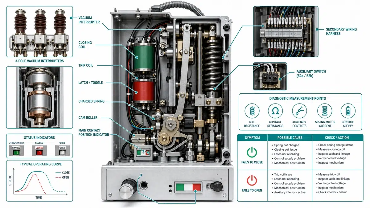
A vacuum circuit breaker that refuses to close or trip should be diagnosed as a system fault, not as an automatic coil replacement. The fastest field workflow separates four root-cause branches: coil circuit, latch and release mechanism, secondary control circuit, and stored-energy mechanism.
Use the checks below to confirm measurable evidence before ordering spares: voltage at the coil terminals during the command, coil resistance, latch engagement, auxiliary contact timing, anti-pumping relay behavior, spring charge, and mechanism travel. Where a value is not in the OEM manual, verify it against the manufacturer’s data sheet or project specification.
The quick diagnosis table below should be completed before dismantling the mechanism or replacing a coil. It is written as a troubleshooting chart: symptom, first test, likely root cause, and next action.
| Symptom | First test | Likely root cause | Next action |
|---|---|---|---|
| Close command present, no closing sound | Measure voltage at closing coil terminals during command | Open fuse, bad auxiliary contact, anti-pumping relay contact open, or broken coil circuit | Trace backward from coil terminal to DC supply and record voltage drop |
| Close sound heard, breaker does not close | Confirm spring charged indication and latch release movement | Close latch binding, trip latch not reset, low spring energy, or mechanism friction | Discharge springs safely, inspect latch/roller/plunger travel, then compare with OEM limits |
| Trip command present, no trip sound | Measure trip coil voltage and coil resistance | Open trip coil, auxiliary 52a contact not making, loose secondary plug, or control supply loss | Isolate coil, verify 52a path, and inspect secondary disconnect pins |
| Trip sound heard, breaker does not open | Check trip bar, pole shaft, linkage, and contact travel | Jammed trip latch, welded contacts, stuck pole shaft, or failed operating rod | Stop service operation and perform mechanical inspection before re-energizing |
| Breaker closes then trips immediately | Review trip input, anti-pumping relay, and auxiliary contact sequence | Protection relay trip input, anti-pump logic error, or mistimed auxiliary contact | Record event sequence and compare with the control schematic |
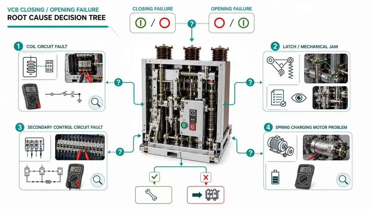
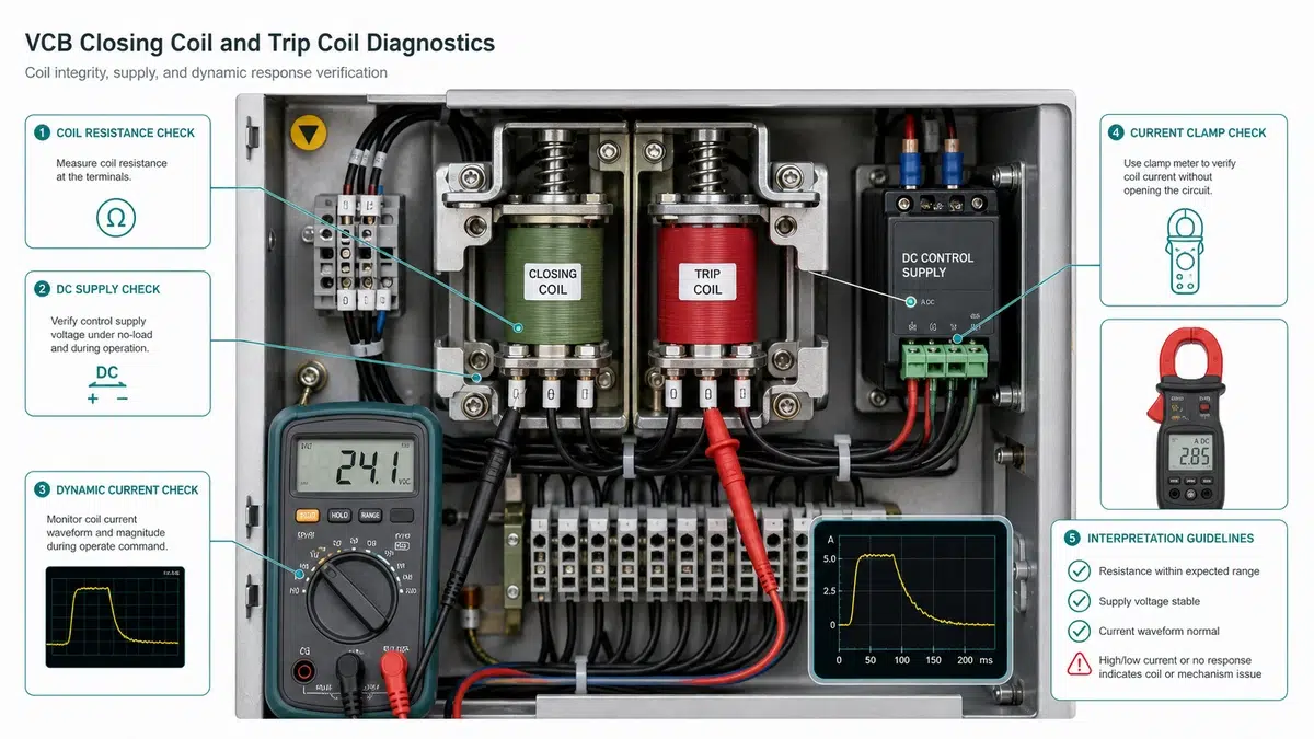
Coil failure is a common VCB closing and opening failure root cause, but the coil should not be condemned until voltage and circuit behavior are checked under command. A coil can test correctly at rest and still fail if the secondary circuit cannot deliver pickup voltage during operation.
Measure voltage across the closing coil or trip coil terminals while the close or trip command is active. Do not rely only on the terminal-block voltage at rest. A low reading at the coil terminals means the fault is upstream of the coil: fuse, wiring joint, auxiliary contact, protection relay output, anti-pumping relay, or control supply.
| Rated control voltage | Minimum at coil terminal | Maximum at coil terminal |
|---|---|---|
| 48 V DC | 38 V DC | 58 V DC |
| 110 V DC | 88 V DC | 132 V DC |
| 220 V DC | 176 V DC | 264 V DC |
| 230 V AC | 184 V AC | 253 V AC |
Isolate the coil circuit and disconnect parallel paths before measuring resistance. Compare the reading with the nameplate or OEM data sheet. Copper winding resistance changes with temperature, so record ambient temperature and whether the coil was recently energized.
| Measured result | Interpretation | Action |
|---|---|---|
| Within +/-10% of nameplate | Coil winding likely intact | Continue to voltage and timing checks |
| Open circuit | Broken winding or lead | Replace the coil |
| More than 20% below nameplate | Possible inter-turn short | Replace coil and verify supply voltage |
| Near zero resistance | Terminal short or suppression component fault | Isolate accessory component and re-test |
Resistance within tolerance does not rule out localized thermal damage. Inspect the bobbin, winding surface, lead exits, and terminal insulation. Brown varnish, cracked insulation, melted leads, or a burned smell are enough to remove the coil from service even if resistance still looks acceptable.
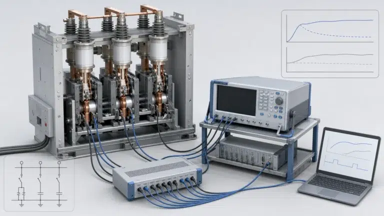
Closing coils are normally short-time devices. If the anti-pumping relay, auxiliary contact, or mechanism position switch keeps the coil energized too long, the coil may burn even though its original quality was acceptable. Record command duration with a timing relay tester, oscilloscope, or current clamp.
The latch and prop assembly converts stored spring energy into controlled contact movement. A healthy coil and a fully charged spring cannot operate the breaker if latch release force is too high, the prop does not reset, or wear has changed the engagement geometry.
Inspect the latch nose, catch plate, roller, pivot pin, and reset spring. Use the OEM limits when available. If no project-specific limit exists, treat the values below as conservative screening indicators and confirm with the manufacturer before final acceptance.
| Check point | Screening limit | What failure suggests |
|---|---|---|
| Latch engagement depth | within +/-0.2 mm of design value | Misadjustment or worn catch face |
| Trip latch wear | more than 0.5 mm wear is high risk | Delayed trip or failure to release |
| Prop pivot pin wear | more than 0.1 mm undersize is high risk | Lost motion and unstable reset |
| Latch roller radial play | more than 0.2 mm is high risk | Inconsistent close or open timing |
| Plunger free travel | less than 1.5 mm is high risk | Coil force is used before latch release |
For model selection context, compare the diagnostic result with the XBRELE vacuum circuit breaker selection page.
Operating time outside the OEM band after coil voltage and spring charge are confirmed is strong evidence of latch or linkage drag. If closing time or opening time is more than 20% above the upper expected value, stop routine operation and inspect the mechanical release train.
Trip-free performance verifies that the breaker will open even when a closing command remains present. Apply rated close command and rated trip command according to the OEM test method. The breaker must close, open, and remain open. Failure points to prop reset timing, catch geometry, or excessive friction in the latch train. IEC 62271-100 and IEEE C37 series documents provide the standards context, but the actual acceptance value must come from the breaker manual.
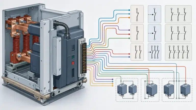
Secondary circuit faults are often misdiagnosed as coil faults because the field symptom is the same: no close, no trip, intermittent operation, or immediate trip after close. The practical method is to work backward from the coil terminals toward the control supply.
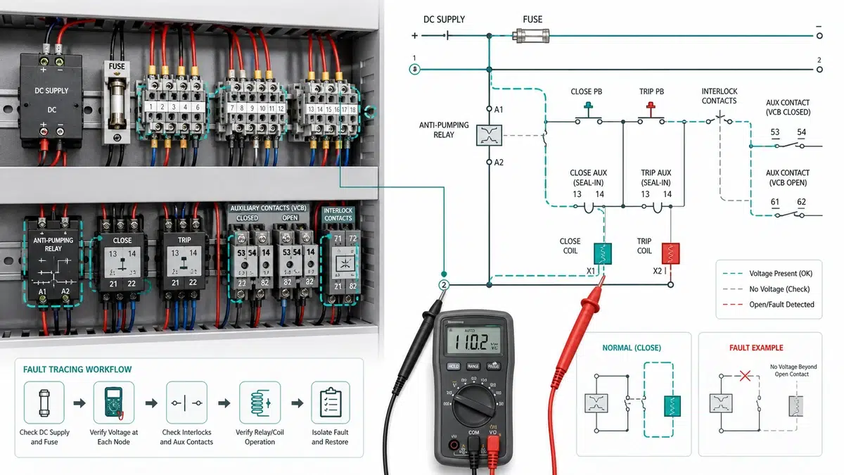
Check charger output, battery voltage, DC fuse continuity, MCB status, and ripple. A supply that is acceptable at the charger but low at the breaker terminal block indicates cable drop, fuse holder resistance, or a loose terminal.
| Check | Acceptable result | Failure direction |
|---|---|---|
| DC bus voltage | rated value within project tolerance | Battery, charger, or upstream fuse |
| Fuse or MCB continuity | closed circuit | Fuse operation or mechanical MCB issue |
| Ripple on DC supply | low and stable | Charger capacitor or rectifier issue |
| Voltage drop to coil | no major drop under command | Wiring joint, relay contact, or plug contact |
Continuity alone is not enough. A corroded terminal can pass a no-load continuity test and still fail under coil current. Measure voltage drop during command and inspect plug pins, terminal screws, cable ferrules, and harness bends. For short control wiring runs, resistance above 0.3 ohm should be investigated.
Auxiliary contacts 52a and 52b must change state at the correct part of the operating stroke. High contact resistance, wrong cam position, or delayed switching can block close/trip logic or keep the coil energized after operation. As a screening rule, investigate any control contact path above 0.5 ohm under the expected control current.
The anti-pumping relay prevents repeated close commands when a close signal is held. If it fails to reset, the next close command is blocked. If it fails to operate, the breaker may repeatedly attempt to close against a fault. Confirm relay coil resistance, pickup, dropout, and holding contact resistance, then compare timing with the control schematic.
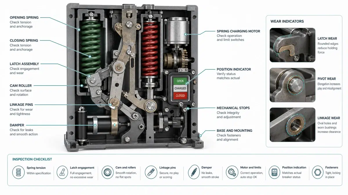
When coil voltage, coil resistance, latch movement, and secondary circuit logic are acceptable, the stored-energy operating mechanism becomes the next suspect. Most faults here develop progressively through wear, dry lubrication, moisture ingress, or high operation count.
Confirm that the spring-charged indicator is correct, the charging motor current is stable, and the charge time has not increased sharply from the maintenance baseline. A charge time increase above 20% is a reason to inspect the motor, gearbox, spring, limit switch, and anti-recharge interlock.
Check pins, bushings, clevises, cam rollers, return springs, and shafts for lost motion. Wear in several small joints can combine into a large travel error. Use only the lubricant specified by the manufacturer; heavy grease in dusty or cold environments can create sluggish operation.
Dashpot oil condition affects opening speed and contact bounce. Milky oil indicates moisture. Rough piston travel indicates contamination or seal damage. A collapsed buffer spring can allow overtravel and inconsistent final contact position.
For standards context, IEEE C37.09 describes standard test procedures for AC high-voltage circuit breakers above 1000 V; use the IEEE C37.09 standard page as context, then verify the exact service limits against the OEM manual and project specification.
The best sequence starts with tests that are fast, non-invasive, and highly diagnostic. Avoid dismantling the mechanism before basic voltage and secondary circuit evidence is recorded.
Every measurement must be tied to an acceptance source. A value from a generic article is only a screening value; the final pass/fail limit should come from the OEM manual, project specification, or the applicable test procedure.
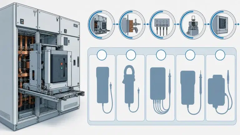
| Tool or record | What it verifies | Acceptance source |
|---|---|---|
| Digital multimeter | Control voltage at terminal block and coil terminal during command | OEM wiring diagram and project control-voltage tolerance |
| Ohmmeter or low-resistance meter | Closing coil, trip coil, auxiliary contact, and plug contact resistance | Nameplate, spare part data sheet, or maintenance baseline |
| Timing analyzer | Closing time, opening time, trip-free sequence, and contact travel consistency | OEM manual, FAT/SAT record, or project test specification |
| Insulation resistance tester | Control circuit insulation and main insulation screening after moisture or contamination | OEM manual and project commissioning specification |
| Contact resistance tester | Main contact path condition when failure symptoms suggest wear or heating | OEM manual, maintenance baseline, and project acceptance record |
| Control schematic and event record | Relay output, anti-pumping path, interlock status, and command sequence | Approved schematic revision and protection relay event log |
| Priority | Check | Typical time | Tool |
|---|---|---|---|
| 1 | Control voltage at terminal block | under 5 min | digital multimeter |
| 2 | Fuse or MCB continuity | under 5 min | continuity tester |
| 3 | Coil terminal voltage during command | 5 to 10 min | multimeter or recorder |
| 4 | Coil resistance | 5 to 10 min | ohmmeter |
| 5 | Auxiliary contact state and resistance | 10 to 15 min | multimeter |
| 6 | Anti-pumping relay pickup/dropout | 10 to 15 min | relay tester or meter |
| 7 | Spring charge and motor current | 10 to 15 min | clamp meter |
| 8 | Latch gap and plunger travel | 15 to 30 min | feeler gauge |
| 9 | Linkage and cam inspection | 20 to 40 min | inspection tools |
| 10 | Contact wear or interrupter checks | 30 to 60 min | OEM test tools |
If manual operation works but electrical operation fails, focus on the coil circuit and secondary circuit. If both close and trip fail, check the shared control supply before testing each coil. If the breaker closes but immediately trips, inspect anti-pumping logic, auxiliary contact sequence, latch engagement, and protection relay trip inputs.
For the control-circuit side of the workflow, use the secondary circuit trip, close, and anti-pumping guide. For commissioning records, keep the VCB FAT/SAT acceptance checklist beside the maintenance file.
A service team found that a 110 V DC breaker would not close from the panel, but the closing coil was not open-circuit. The terminal block measured 109 V DC at rest. During the close command, the measured voltage at the coil terminal fell to 61 V DC while the terminal block remained above 105 V DC.
The diagnostic example points away from an automatic coil replacement. The measured drop indicates high resistance between the terminal block and coil terminal: a loose plug pin, oxidized auxiliary contact, weak relay contact, or damaged control wire. The corrective action is to split the circuit into short test sections, record voltage under command at each node, repair the high-resistance point, and repeat the close test before ordering a replacement coil.
When the root cause is confirmed, the repair decision should be based on service risk, compatibility, and lead time, not only part price.
| Data required | Why it matters |
|---|---|
| Rated voltage and insulation level | Prevents insulation under-rating |
| Rated current | Confirms thermal capacity |
| Short-circuit breaking current | Confirms fault clearing capability |
| Making current | Confirms close-on-fault duty |
| Operating sequence | Confirms duty and reclose suitability |
| Control voltage | Matches close/trip coils and motor |
| Trip coil count | Matches protection scheme |
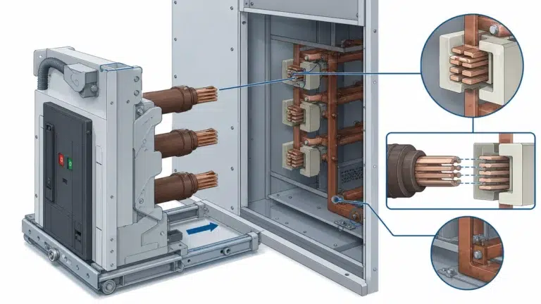
| Cassette or fixed-frame dimensions | Confirms physical interchangeability |
| Secondary plug drawing | Confirms control compatibility |
Replace the complete breaker when the vacuum interrupter path is no longer serviceable, the mechanism frame or main shaft is damaged, compatible OEM parts are unavailable, or the breaker is near the mechanical endurance limit and is installed in a critical feeder.
Targeted spares are appropriate when the root cause is isolated to a coil, auxiliary contact block, anti-pumping relay, charging motor, latch roller, or spring accessory. A practical spare package for critical feeders includes close coil, trip coil, anti-pumping relay, charging motor, auxiliary switch, latch roller set, and common plug contacts.
Complete the closing and opening failure root cause tree before raising a purchase order. Record coil voltage, coil resistance, latch evidence, spring charge status, and secondary circuit continuity. For quotation data, use the VCB RFQ checklist.
Low voltage at the closing coil terminals during the command pulse is the most common first check. If terminal-block voltage is normal but coil-terminal voltage drops, inspect auxiliary contacts, fuses, wiring joints, and anti-pumping relay contacts before replacing the coil.
Isolate each coil and measure resistance against the nameplate or OEM data sheet. An open reading confirms a broken winding or lead. A very low reading suggests an inter-turn short. If both coils read correctly, the fault is usually in the shared secondary circuit.
Manual operation may be possible during isolated maintenance if the OEM manual allows it and the mechanism is in the correct charged or discharged state. Manual operation does not prove that the electrical circuit is healthy.
Measure closing and trip coil resistance during scheduled maintenance and after any failed close or trip event. Record temperature, test date, and instrument so the trend can be compared across maintenance cycles.
If the charged indicator is normal but the breaker will not operate, inspect latch engagement, cam roller movement, linkage lost motion, and spring-release sequence before condemning the spring.
Replace the breaker when the interrupter path, frame, shaft, or compatibility situation creates more risk than targeted repair. Repair is usually reasonable when the fault is isolated to coils, relays, auxiliary contacts, motors, or latch accessories.
The main risks are cassette fit, secondary plug mismatch, auxiliary contact timing, closing spring energy, and contact-gap differences. Confirm dimensions, ratings, and secondary circuit compatibility in writing before procurement.