Need Full Specifications?
Download our 2025 Product Catalog for detailed drawings and technical parameters of all switchgear components.
Get CatalogDownload our 2025 Product Catalog for detailed drawings and technical parameters of all switchgear components.
Get CatalogDownload our 2025 Product Catalog for detailed drawings and technical parameters of all switchgear components.
Get Catalog
The contact gap in a vacuum interrupter—measured between fixed and moving contact faces when fully open—determines whether your circuit breaker withstands recovery voltage or fails during the next fault. Get this parameter wrong, and you compromise either dielectric integrity (too narrow) or mechanism longevity (too wide).
Factory calibration establishes these dimensions under controlled conditions with precision fixtures and calibrated instruments. Field reality involves dust, vibration-induced drift, and technicians working from elevated platforms with portable tools. This guide separates what you can verify and adjust on-site from what requires factory return—because knowing that boundary prevents both unnecessary downtime and dangerous improvisation.
Contact gap directly governs two performance parameters in every vacuum circuit breaker. First, dielectric withstand capability: vacuum exhibits nonlinear breakdown characteristics, with gaps below 4 mm showing near-linear voltage-distance relationships that flatten at larger separations. Second, arc extinction performance: during interruption, contact separation speed and final gap determine how quickly the arc extinguishes at current zero.
For 12 kV rated interrupters, contact gaps typically fall between 10–12 mm. At 40.5 kV, expect 16–20 mm. These values appear on nameplates—never assume cross-compatibility between voltage classes.
Mechanical alignment refers to how precisely the moving contact travels toward the fixed contact face. The moving assembly should approach along a centerline passing through the center of the fixed contact. Even 1 mm deviation creates edge-loading during contact make, accelerating localized erosion.
Related parameters form an interconnected system:
| Parameter | Definition | Typical 12 kV Values |
|---|---|---|
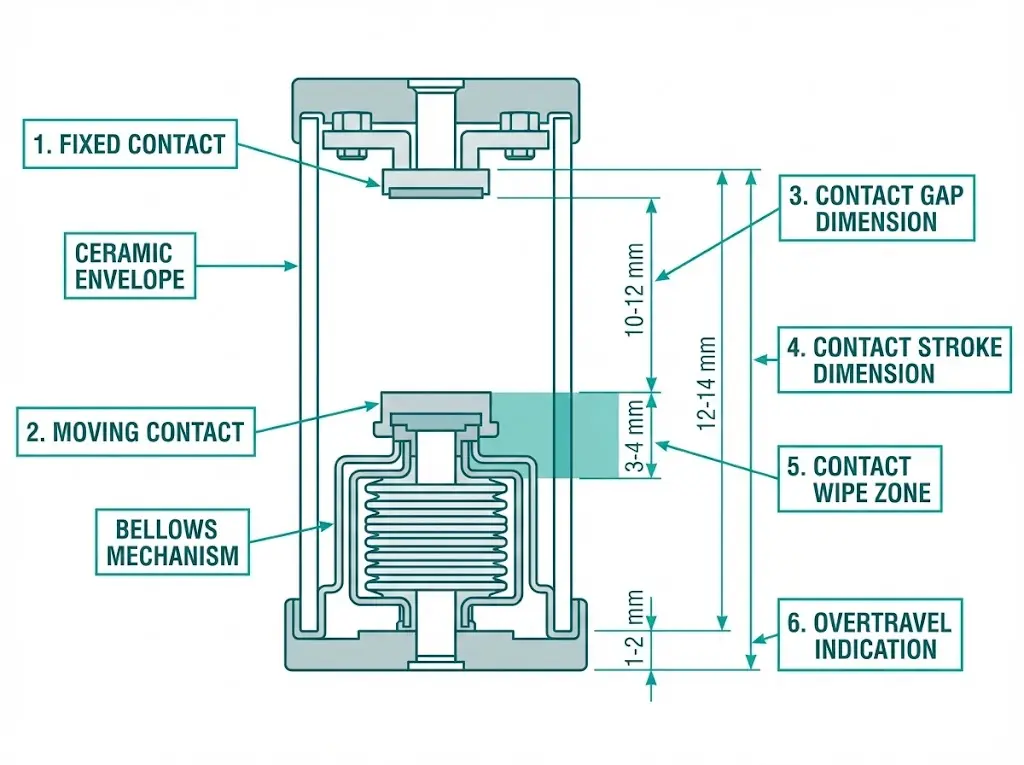
| Contact gap | Open-position separation | 10–12 mm |
| Contact stroke | Total moving contact travel | 12–14 mm |
| Contact wipe | Compression after initial touch | 3–4 mm |
| Overtravel | Mechanism travel beyond wipe | 1–2 mm |
Contact wipe generates pressure—typically 1,500–2,500 N for 12 kV contacts. As contacts erode through switching operations, wipe decreases while gap increases. The mechanism stroke remains constant; it simply distributes differently between gap and wipe as material wears away.
Factory calibration occurs with the vacuum interrupter, operating mechanism, and insulating frame assembled as a coordinated unit. Understanding what gets set—and why it stays set—clarifies field adjustment boundaries.
Geometric alignment positions the moving contact travel axis through the center of the fixed contact face. Factory tolerance typically holds within ±0.5 mm of centerline using precision fixtures unavailable in field settings.
Mechanism linkage calibration establishes stroke length, trip latch engagement depth, and spring preload (for spring-operated mechanisms). These adjustments interact—changing one shifts others. Factory procedures specify adjustment sequence, torque values, and verification measurements at each step.
Three-phase timing synchronization ensures all poles of a VS1 series indoor VCB or similar design close and open together. Pole disagreement—contacts operating at different times—creates transient overvoltages, unequal current sharing, and increased mechanism stress. Factory tolerance requires all poles within 2 ms of each other per IEC 62271-100 requirements.
| Parameter | Factory Set | Field Adjustable |
|---|---|---|
| Contact centerline alignment | Yes | No |
| Contact gap (nominal) | Yes | Verify only |
| Pole synchronization | Yes | No |
| Trip latch engagement | Yes | Limited |
| Auxiliary switch timing | Initial | Yes |
The factory tooling advantage extends beyond precision. Calibration requires simultaneous adjustment across multiple parameters that field conditions cannot replicate without specialized equipment.
[Expert Insight: Factory Calibration Reality]
- Units shipped with actual measured values (not generic specs) show 23% fewer early-life failures in industrial applications
- Factory calibration accounts for contact erosion projections based on anticipated switching duty
- Mechanism linkage tolerances of ±0.1 mm require laser displacement sensors rarely available on-site
- Three-pole synchronization adjustment demands coordinated access to all operating shafts simultaneously
Field work divides into verification measurements (always permissible) and adjustments (narrow scope). Every maintenance interval should include systematic verification that preserves factory calibration integrity.
Contact gap direct measurement:
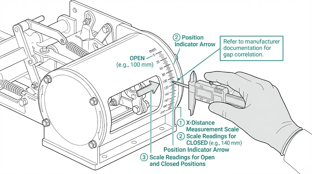
X-distance correlation method avoids opening the interrupter enclosure. Many manufacturers provide external measurement points correlating to internal contact position—a scale marked on the mechanism housing indicates travel. Refer to manufacturer documentation for gap correlation, accounting for contact erosion effects.
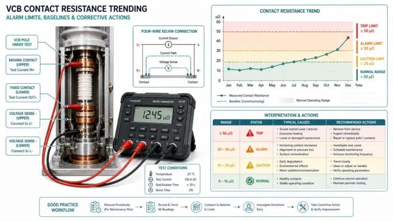
Contact resistance testing using a micro-ohmmeter (≥100 A DC minimum) reveals erosion and contamination conditions. New contacts typically measure 20–50 μΩ. Values approaching 80 μΩ warrant attention; exceeding 100 μΩ indicates condemning-level erosion.
Timing verification with portable analyzers captures close and open times at millisecond resolution. Compare against factory specifications—typically 40–70 ms close time, 20–40 ms open time for spring-operated 12 kV units. Per IEEE C37.09 test procedures, timing measurements should include contact bounce assessment.
| Measurement | Instrument | Acceptable Range (12 kV) |
|---|---|---|
| Contact gap | Depth gauge | 10–12 mm |
| Contact resistance | Micro-ohmmeter (≥100 A) | <80 μΩ |
| Close time | Timing analyzer | 40–70 ms |
| Open time | Timing analyzer | 20–40 ms |
Understanding these measurement approaches proves essential when evaluating vacuum circuit breaker ratings against actual field-measured performance.
Some adjustments remain field-permissible when performed by trained technicians with proper documentation.
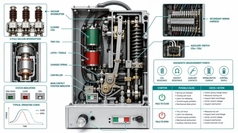
Trip latch reset position: If the breaker fails to latch closed, minor adjustment of trip latch engagement may restore function. Turn adjustment screw in 1/4-turn increments, verifying latch engagement force with a pull gauge after each adjustment.
Auxiliary switch timing: Position indication switches must accurately reflect breaker state for protection coordination. These switches include adjustment provisions and don’t affect primary contact operation.
Closing spring preload verification: Spring-operated mechanisms include inspection windows showing charge status. Preload should match factory specifications—verification yes, adjustment rarely.
Clear boundaries exist. Field adjustment cannot fix:
| Condition | Field Action | Factory Required |
|---|---|---|
| Breaker won’t latch | Adjust trip latch | If adjustment fails |
| Position indication wrong | Adjust auxiliary switches | — |
| Contact gap out of spec | Document only | Yes |
| Timing out of sync | Document only | Yes |
| High contact resistance | Document only | Replace interrupter |
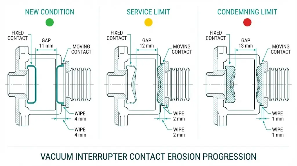
Contact erosion consumes wipe distance first, then increases gap. A systematic trending approach predicts replacement timing before condemning limits force emergency outages.
During each fault interruption, arc energy vaporizes contact material—typically 0.05–0.1 mm per 10 kA fault clearing event. After 10,000 mechanical operations, cumulative erosion may reduce effective gap by 1–3 mm. High-frequency switching applications (capacitor banks, arc furnace supply) accelerate this progression dramatically compared to utility distribution averaging 2–5 operations monthly.
| Condition | Contact Gap | Wipe | Resistance | Action |
|---|---|---|---|---|
| New | 11 mm | 4 mm | 30 μΩ | Record baseline |
| Service limit | 12 mm | 2 mm | 60 μΩ | Plan replacement |
| Condemning | 13 mm | 1 mm | 100 μΩ | Remove from service |
Values shown for typical 12 kV, 25 kA interrupter. Actual limits vary by manufacturer.
Plotting contact gap versus cumulative switching operations reveals erosion rate. Linear regression projects remaining service life, enabling replacement parts procurement before reaching condemning thresholds.
[Expert Insight: Erosion Rate Realities]
- Mining installations with 50+ daily operations show 5× faster erosion than utility distribution applications
- Contact resistance trending often detects erosion before gap measurements show deviation
- Baseline documentation during commissioning enables meaningful comparison—without it, trending provides limited value
- Wipe reduction below 2 mm typically precedes gap problems by 6–12 months in high-duty applications
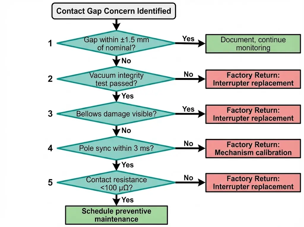
Certain conditions exceed field repair capability. Attempting adjustment creates greater risk than the original problem.
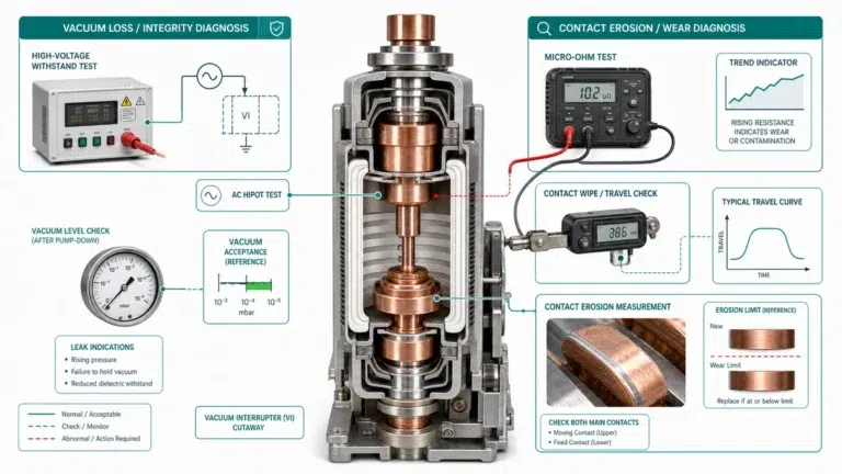
Vacuum loss: Power-frequency withstand test failure across open contacts indicates vacuum degradation. Field repair is impossible—the interrupter requires replacement. This condition may present as increased X-ray emission during high-voltage testing or visible internal arcing discoloration.
Bellows damage: Visible cracks, tears, or deformation of the metal bellows that maintains vacuum seal compromises long-term integrity. Even minor damage warrants interrupter replacement.
Alignment deviation exceeding 1 mm: Centerline offset creates uneven wear and potential mechanical binding. Correction requires factory fixtures that maintain all related parameters simultaneously.
Mechanism wear: Excessive play in linkage pins, bushings, or bearings prevents calibration stability. Worn linkages cannot hold adjustment.
Contact bounce exceeding 2 ms: Measured during timing tests as oscillation after initial contact make. Excessive bounce indicates worn dashpot or incorrect closing velocity requiring mechanism overhaul.
Return-to-Factory Checklist:
Installation environment determines verification frequency more than calendar intervals.
Vibration exposure from nearby rotating machinery loosens fasteners and accelerates linkage wear. Breakers mounted on structures subject to continuous vibration require monthly verification versus annual intervals for stable installations. Mining applications and facilities near rail corridors show fastest drift rates.
Temperature cycling exceeding 30°C daily range creates differential expansion between metallic components and insulating supports. Include ambient temperature in measurement records; compare readings taken at similar temperatures for valid trending.
High switching duty accelerates erosion. Applications exceeding 10 operations daily warrant quarterly gap trending rather than annual spot-checks. Capacitor bank switching and motor starting applications fall into this category.
Contamination ingress increases mechanism friction, affecting contact travel consistency. External mechanism enclosures in dusty environments require periodic cleaning beyond standard inspection protocols.
| Environment | Effect | Verification Interval |
|---|---|---|
| Continuous vibration | Fastener loosening | Monthly |
| Wide temperature swing | Dimensional drift | Quarterly with temperature record |
| High switching frequency | Accelerated erosion | Quarterly trending |
| Dusty/contaminated | Mechanism friction | Annual cleaning + inspection |
Contact gap calibration represents one element of comprehensive vacuum circuit breaker quality. At XBRELE, every breaker ships with factory calibration records documenting measured contact gap, stroke, wipe, timing, and resistance values for each phase—actual measurements, not generic specifications.
Our technical support team provides field measurement guidance, calibration documentation packages, and return-to-factory services when field adjustment limits are exceeded. Training programs tailored to your installed fleet ensure maintenance personnel understand both verification procedures and adjustment boundaries.
Contact XBRELE’s vacuum circuit breaker manufacturing team for technical specifications, calibration data sheets, or maintenance training programs.
Q: How often should contact gap be measured on a vacuum circuit breaker?
A: Annual measurement suits most installations, but high-duty applications exceeding 5,000 operations yearly or environments with continuous vibration warrant semi-annual verification to catch drift before it affects performance.
Q: Can contact gap be adjusted in the field if measurements show deviation?
A: Contact gap is factory-set through mechanism linkage calibration that affects multiple interdependent parameters; field technicians should document deviations and schedule factory service rather than attempting adjustment.
Q: What does X-distance measurement indicate on a VCB mechanism?
A: X-distance provides an external reference correlating to internal contact position, allowing gap verification without opening the interrupter enclosure—manufacturer documentation provides the specific correlation for each model.
Q: At what contact resistance value should a vacuum interrupter be replaced?
A: Resistance exceeding 100 μΩ (measured with ≥100 A DC injection) generally indicates condemning-level erosion, though manufacturer specifications may vary; trending from baseline values provides earlier warning than absolute thresholds.
Q: Why can’t pole synchronization be corrected in the field?
A: Synchronization adjustment requires coordinated modification across all three operating shafts using fixtures that maintain related parameters simultaneously—field correction without proper tooling typically worsens the imbalance.
Q: How does contact erosion affect gap and wipe measurements differently?
A: Erosion reduces wipe (post-touch compression) first while gap remains stable, then increases open-position gap as wear progresses—monitoring both parameters reveals erosion stage more accurately than either measurement alone.
Q: What environmental factor causes fastest contact gap drift?
A: Continuous vibration from nearby rotating machinery accelerates both fastener loosening and linkage wear, causing measurably faster calibration drift than temperature cycling or contamination in most industrial installations.