Need Full Specifications?
Download our 2025 Product Catalog for detailed drawings and technical parameters of all switchgear components.
Get CatalogDownload our 2025 Product Catalog for detailed drawings and technical parameters of all switchgear components.
Get CatalogDownload our 2025 Product Catalog for detailed drawings and technical parameters of all switchgear components.
Get Catalog
Surface contamination accounts for a disproportionate share of outdoor MV equipment failures—particularly in coastal zones, industrial corridors, and agricultural regions where airborne deposits accumulate faster than natural washing removes them.
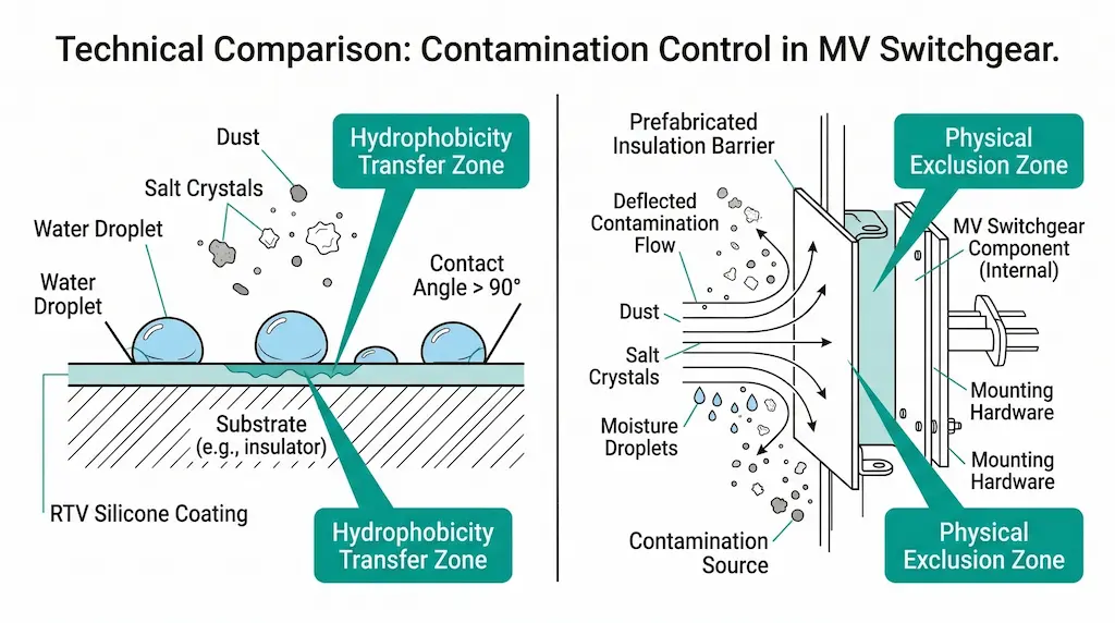
Two field-proven countermeasures dominate pollution mitigation practice: RTV (Room Temperature Vulcanizing) silicone coatings and physical insulation barriers. RTV modifies surface behavior. Barriers physically block contaminant access. Both extend service reliability, but through fundamentally different mechanisms that determine their effectiveness across varying site conditions.
Selecting between them—or combining both—depends on your specific pollution profile, maintenance capacity, and equipment constraints. This comparison draws from field realities rather than laboratory ideals.
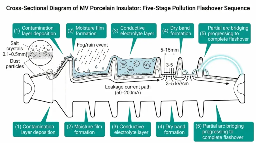
Pollution flashover occurs when contaminated insulator surfaces become conductive under moisture, creating leakage currents that eventually arc across the creepage path. Understanding this mechanism is essential before comparing protective strategies.
The process follows a predictable sequence. Airborne contaminants—industrial emissions, sea salt, agricultural dust—deposit on insulator surfaces over weeks or months. These deposits contain conductive ions including Na⁺, Cl⁻, and SO₄²⁻. During moisture events (fog, light rain, humidity exceeding 80% RH), contaminants dissolve and form a conductive electrolyte layer.
According to IEC 60815-1 (Selection and dimensioning of high-voltage insulators intended for use in polluted conditions), surface conductivity of the contamination layer typically ranges from 10−6 to 10−3 S at equivalent salt deposit density (ESDD) levels of 0.03–0.25 mg/cm². This conductivity initiates leakage currents that can reach 50–200 mA on MV insulators before flashover occurs.
Leakage current creates localized heating along the insulator surface. Areas with higher current density—particularly near shed edges and regions with thinner moisture films—experience accelerated evaporation. This drying action forms “dry bands” with resistance values 10–100× higher than wet regions.
When voltage concentrates across these narrow dry bands (typically 5–15 mm wide), the electric field intensity can exceed 3–5 kV/cm. Partial arcs bridge the dry bands, creating visible scintillation. If conditions persist, arcs extend progressively until complete flashover spans the creepage path.
Both RTV coatings and insulation barriers interrupt this mechanism—but through distinctly different physical principles.
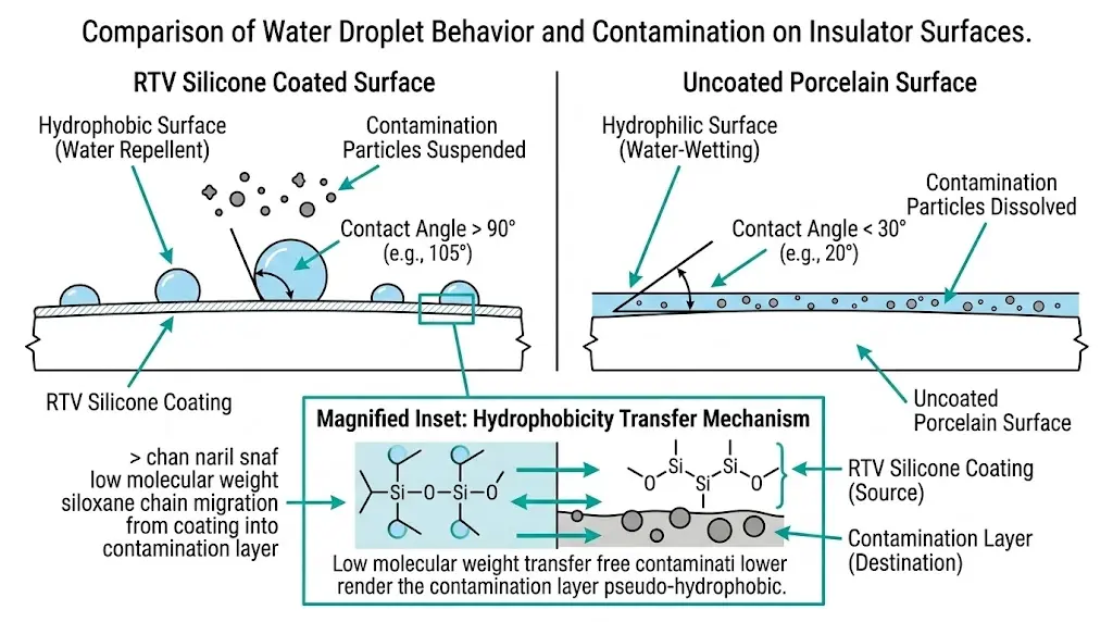
RTV silicone coatings achieve pollution resistance through hydrophobicity, creating a water-repellent surface that prevents continuous conductive film formation. The silicone polymer continuously migrates low-molecular-weight chains to the surface, restoring hydrophobicity even after contamination deposits.
In deployments across 75+ coastal substations in high-salinity environments, RTV coatings maintained contact angles above 90° for 8–12 years before requiring reapplication. This “hydrophobicity transfer” phenomenon—where silicone migrates into the contamination layer itself—distinguishes RTV from simple water-resistant coatings.
Proper RTV installation demands meticulous surface preparation. The substrate must be cleaned to remove all contaminants, with surface roughness maintained between Ra 3.2–12.5 μm for optimal bonding. Coating thickness should range from 0.3–0.5 mm per layer, with most applications requiring 2–3 coats for 1.0–1.5 mm total thickness.
Ambient conditions matter significantly: temperatures between 5–35°C and relative humidity below 85% ensure proper curing. Complete cure requires 24–72 hours depending on formulation—during which surfaces remain vulnerable to contamination.
RTV coatings excel against soluble salts and marine contamination but show weaknesses in specific conditions:
[Expert Insight: RTV Coating Selection]
- Specify high-temperature-vulcanized (HTV) silicone base for applications above 40°C ambient
- Request accelerated UV aging test data (minimum 2,000 hours) for installations above 1,500 m elevation
- Verify hydrophobicity recovery testing per IEC 62217 before accepting any coating product
- Budget for surface preparation costs equal to 30–40% of coating material cost
Insulation barriers function through physical obstruction—preventing pollutants from reaching critical creepage paths rather than modifying surface properties. These barriers extend effective leakage distance by 15–40% depending on design configuration, upgrading pollution performance class without modifying the base insulator.
Prefabricated barriers mount directly onto existing outdoor MV switchgear structures, eliminating wet-application variables. Installation involves mechanical fastening or adhesive bonding, with clearance distances maintained according to voltage class—minimum 125 mm phase-to-phase spacing for 12 kV applications.
Physical barriers prove superior in specific environments:
Field testing in mining operations showed barrier replacement cycles averaging 6 years versus 12-year RTV recoating intervals under comparable dust exposure—but barriers eliminated the specialized surface preparation requirements.
Barrier effectiveness depends on geometry and spacing. Minimum creepage distances of ≥25 mm/kV apply for pollution levels corresponding to IEC 60815 Class III (heavy contamination). Critical installation errors include insufficient drainage provisions (trapped moisture accelerates degradation) and inadequate mechanical clearances that create new flashover paths.
Insulation barriers provide mechanical shielding against direct contamination accumulation but lack hydrophobic properties. Their effectiveness depends on barrier geometry and spacing, typically requiring minimum creepage distances of ≥25 mm/kV for pollution levels corresponding to IEC 60815 Class III (heavy contamination).
When selecting between these pollution mitigation approaches, environmental conditions and operational constraints determine the optimal choice. Neither solution universally outperforms the other.
| Parameter | RTV Coating | Insulation Barriers |
|---|---|---|
| Protection mechanism | Surface modification (hydrophobicity) | Physical exclusion |
| Typical service life | 8–15 years | 15–25 years |
| ESDD tolerance | Up to 0.35 mg/cm² | Up to 0.25 mg/cm² |
| Salt fog effectiveness | Excellent | Good |
| Abrasive dust effectiveness | Moderate | Excellent |
| Installation complexity | Field-applied (spray/brush) | Factory or field mounting |
| Immediate protection | No (24–72 hr cure) | Yes |
| Initial cost per insulator | $15–40 | $80–200 |
| Site Condition | Favors RTV Coating | Favors Insulation Barriers |
|---|---|---|
| Pollution type | Soluble salts, marine spray | Abrasive dust,ite particles |
| Wetting frequency | High (coastal fog, frequent rain) | Low (arid, desert) |
| Maintenance access | Limited, remote locations | Regular inspection possible |
| Creepage adequacy | Marginal (needs 25–40% boost) | Severely inadequate |
| Workforce skills | Coating application available | General mechanical skills |
| Budget profile | Lower upfront, higher lifecycle | Higher initial, lower lifecycle |
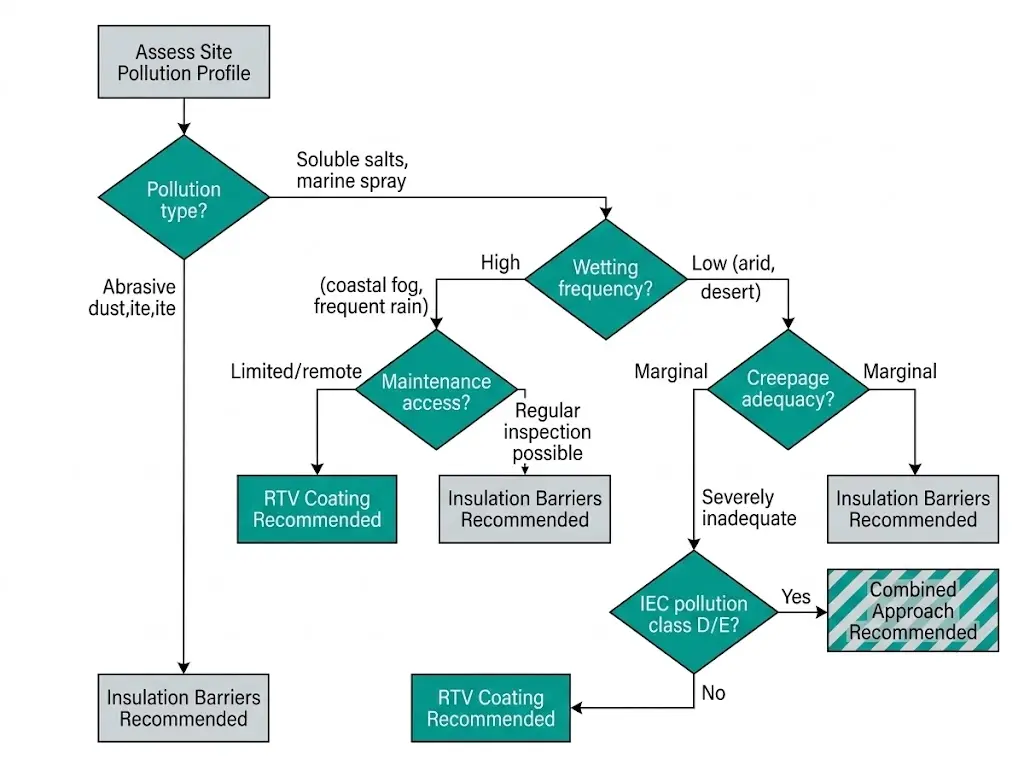
Sites with IEC pollution level “d” (very heavy, ESDD > 0.6 mg/cm²) often benefit from layered protection. Barriers reduce gross contamination accumulation while RTV coating on protected surfaces provides secondary defense against residual deposits. In coastal substation deployments, this combined approach achieved zero flashover events over 6-year observation periods where single-method installations experienced 1–3 annual events.
For medium-voltage vacuum circuit breakers in these severe environments, specifying both methods at initial installation typically costs less than retrofitting after contamination-related failures occur.
[Expert Insight: Combined Protection Strategy]
- Apply RTV coating to barrier-protected surfaces—not as redundancy, but to address the 10–15% of fine contamination that bypasses physical barriers
- Inspect barrier drainage paths before each wet season; blocked drainage accelerates RTV degradation
- Document baseline hydrophobicity measurements at installation for comparison during maintenance inspections
- Consider silicone-based barrier materials (rather than SMC or epoxy) for inherent hydrophobicity in extreme marine environments
Total cost of ownership often surprises engineers who focus only on initial installation expenses. Over a 20-year equipment lifecycle, RTV coatings and insulation barriers frequently reach similar total costs—but through different expenditure patterns.
| Year | Activity | Cost Factor |
|---|---|---|
| 0 | Initial application | 1.0× |
| 3 | Hydrophobicity inspection | 0.05× |
| 5 | Touch-up degraded areas | 0.2× |
| 8 | Full recoating (first cycle) | 0.8× |
| 12 | Inspection + spot repair | 0.15× |
| 15 | Full recoating (second cycle) | 0.8× |
| Total | ~3.0× |
| Year | Activity | Cost Factor |
|---|---|---|
| 0 | Installation | 2.5× |
| 2 | Hardware inspection | 0.02× |
| 5 | Cleaning + fastener check | 0.1× |
| 10 | Gasket/seal replacement | 0.15× |
| 15 | Cleaning + structural assessment | 0.1× |
| Total | ~3.0× |
Field experience reveals costs frequently missed in initial analysis:
Environmental factors beyond pollution type significantly influence mitigation method selection. Site-specific conditions can shift the optimal choice even when pollution characteristics favor one approach.
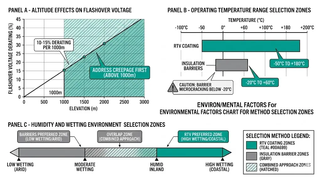
Reduced air density at elevations above 1,000 m lowers flashover voltage—a 10–15% derating per 1,000 m above sea level is typical for MV equipment. Address creepage distance adequacy first, then select the mitigation method. An insulator marginally adequate at sea level may require both extended creepage (via barriers) and surface protection (via RTV) at altitude.
RTV formulations maintain flexibility across −50°C to +180°C operating ranges, but certain barrier materials exhibit microcracking below −20°C. For equipment experiencing severe thermal cycling, coating flexibility prevents the delamination that compromises barrier integrity over time.
Conversely, dark-colored barriers in high-ambient-temperature installations (>45°C) can create localized hot spots. Specify light colors or reflective finishes where solar heating combines with equipment thermal output.
Biological growth poses unique challenges in tropical installations. Algae, fungi, and lichen colonize RTV surfaces, potentially degrading hydrophobicity faster than contamination alone. Barrier systems may prove more durable where biological activity is high—though drainage provisions become critical to prevent moisture retention.
For installations requiring compliance with international standards, CIGRE pollution performance guidelines provide comprehensive technical resources addressing these environmental variables.
Selecting pollution mitigation strategies starts with equipment engineered for harsh environments. XBRELE manufactures medium-voltage switchgear and components designed for challenging outdoor conditions:
Our engineering team provides site-specific recommendations based on your pollution survey data, altitude, temperature range, and maintenance capabilities.
Request a technical consultation for your outdoor MV installation from a vacuum circuit breaker manufacturer with field experience across diverse pollution environments—we help you specify equipment that minimizes ongoing mitigation costs while maintaining reliable operation.
Q: Can RTV coating be applied to energized MV equipment?
A: No—RTV application requires complete de-energization and thorough surface cleaning; applying to inadequately prepared surfaces causes adhesion failure within 2–3 years regardless of coating quality.
Q: How do I know when RTV coating needs replacement?
A: Perform spray-method hydrophobicity testing annually; when water no longer beads (contact angle drops below 50°) or visible chalking and cracking appear, schedule recoating within the next maintenance window.
Q: Do insulation barriers eliminate contamination cleaning requirements?
A: Barriers reduce but do not eliminate maintenance—protected surfaces still accumulate fine particles requiring periodic cleaning, though at 2–3× longer intervals than unprotected equipment.
Q: Which method performs better near cement plants or mines?
A: Insulation barriers typically outperform RTV coatings in these environments because calciumite andite particles mechanically abrade silicone surfaces, reducing coating life by 40–60%.
Q: Can both methods be combined on the same equipment?
A: Yes—combined protection suits severe pollution environments (IEC Class D/E), with barriers reducing gross contamination load while RTV addresses residual fine particles that bypass physical shielding.
Q: What is the realistic service life difference between these methods?
A: RTV coatings typically require full replacement at 8–15 years depending on UV exposure and pollution severity; quality insulation barriers provide 15–25 years of service with periodic seal and fastener maintenance.
Q: Does high altitude affect pollution mitigation selection?
A: Altitude reduces air dielectric strength, lowering flashover voltage by 10–15% per 1,000 m; ensure creepage distance adequacy first, then select the mitigation method appropriate for your pollution type and maintenance capacity.