Need Full Specifications?
Download our 2025 Product Catalog for detailed drawings and technical parameters of all switchgear components.
Get CatalogDownload our 2025 Product Catalog for detailed drawings and technical parameters of all switchgear components.
Get CatalogDownload our 2025 Product Catalog for detailed drawings and technical parameters of all switchgear components.
Get Catalog
A circuit breaker’s ability to interrupt fault current dominates most specification discussions. Breaking capacity appears on every datasheet, every tender document, every engineering checklist. Yet another rating determines survival during an equally violent event—one that occurs before the first current zero, before arc interruption physics even apply.
That rating is making capacity.
When a breaker closes directly into an active fault, the contacts must withstand the first asymmetrical current peak—a transient that exceeds steady-state fault levels by 150% or more. This peak arrives within 5–10 milliseconds of contact touch, generating electrodynamic forces that can weld contacts together or deform operating mechanisms. A breaker that fails this test doesn’t trip. It doesn’t protect. It becomes the failure point.
This guide explains what making capacity means in precise engineering terms, why the first half-cycle creates unique mechanical stress, when closing-on-fault events actually occur in service, and how to specify peak making current correctly using IEC 62271-100 methodology.
Making capacity—formally “rated short-circuit making current” per IEC standards—defines the maximum peak current a circuit breaker can close onto during a fault and successfully latch without mechanical damage or contact welding.
The critical distinction from breaking capacity lies in both timing and units.
Breaking capacity addresses what happens after fault current establishes: the breaker must interrupt current at a natural zero crossing, managing arc energy and dielectric recovery. This rating uses kA RMS because it reflects thermal stress from sustained fault current.
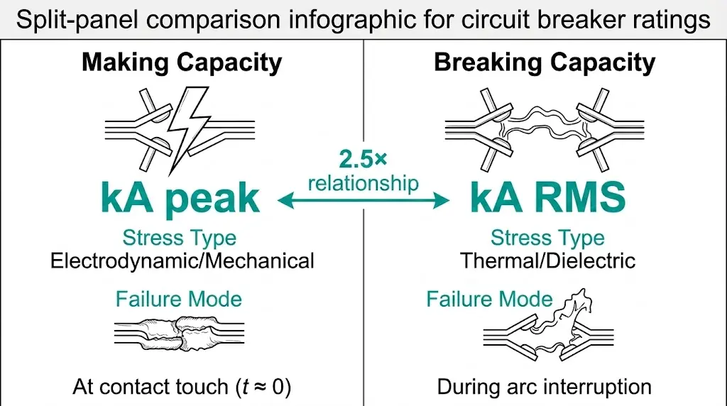
Making capacity addresses what happens at the instant of closing: the mechanism must withstand the first asymmetrical current peak, which contains maximum DC offset. This rating uses kA peak because instantaneous mechanical forces—not sustained thermal load—determine survival.
The relationship between these ratings follows a standard multiplier. For systems with typical X/R ratios around 14:
Making Capacity (kA peak) = 2.5 × Breaking Capacity (kA RMS)
A medium-voltage vacuum circuit breaker rated for 40 kA breaking capacity therefore carries a making capacity of 100 kA peak. This isn’t arbitrary—it reflects asymmetrical fault current physics.
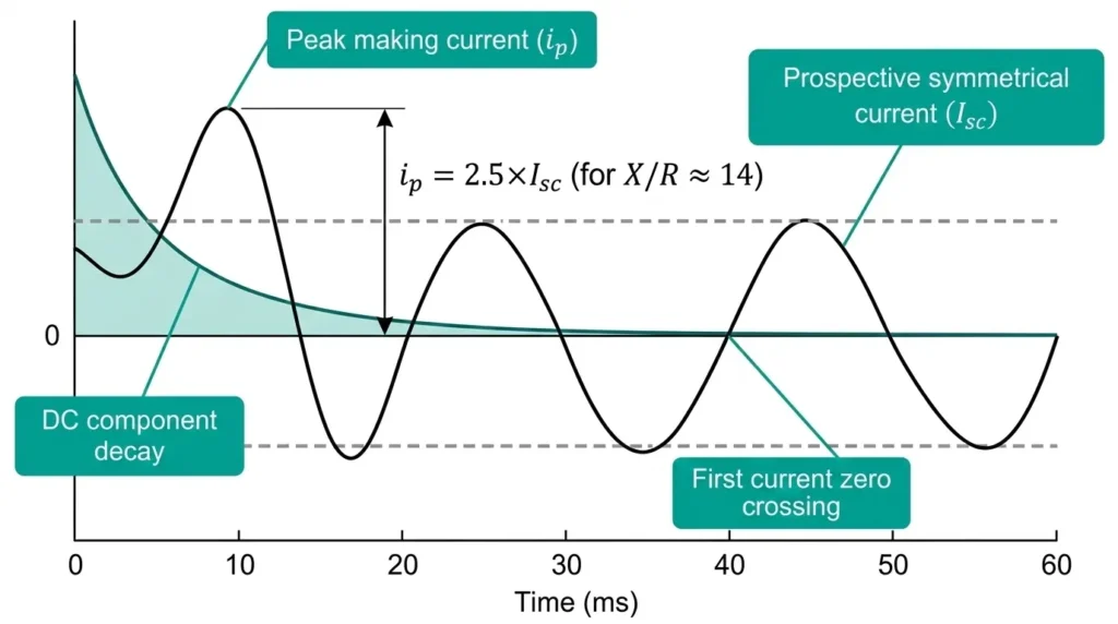
When a fault initiates at an unfavorable point on the voltage waveform, the resulting current contains a DC component that decays over several cycles. The first peak of this asymmetrical waveform—occurring roughly 10 ms after fault inception at 50 Hz—reaches 2.5× the eventual symmetrical RMS value. A breaker closing into this fault handles that peak, not the lower steady-state value.
The consequence of inadequate making capacity is mechanical failure. Contacts weld from localized heating at microscopic contact points. Operating mechanism components bend or fracture from electromagnetic forces. The breaker fails to respond when protection commands a trip—transforming a recoverable fault into equipment destruction.
The physics of closing-on-fault demand respect. Three phenomena converge to create stress levels that far exceed normal switching operations.
The electromagnetic repulsion force follows the relationship F ∝ I², meaning a 40 kA fault generates 16× the force of a 10 kA fault. Contact holders and operating mechanisms must be dimensioned for peak making current (Ipeak) values specified in IEC 62271-100, typically calculated as 2.5 × Isc(rms) for 50 Hz systems with DC time constants below 45 ms.
At 80 kA peak versus 40 kA peak, force increases fourfold—not twofold. These forces act to repel contacts apart (blow-off) and stress the operating mechanism throughout its structure. Contact assemblies in typical 12 kV vacuum interrupter designs experience repulsive forces of 15–25 kN during severe closing-on-fault events.
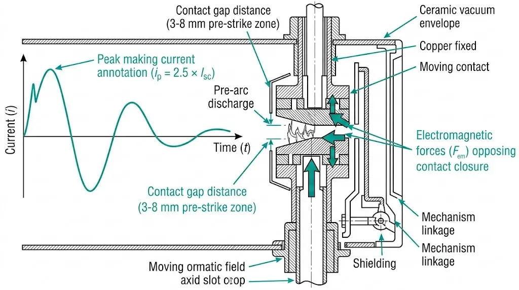
As contacts approach, dielectric breakdown occurs across the narrowing gap. Pre-arc duration runs 1–4 ms depending on closing speed and gap geometry. Arc energy concentrates on a small surface area before full contact engagement occurs.
For vacuum circuit breakers, pre-strike arcing initiates at gap distances of 3–8 mm depending on system voltage. This arc establishes current flow before mechanical contact, subjecting the closing mechanism to full fault-level forces throughout the final approach phase.
Mechanical bounce creates repeated micro-separations after initial touch. Each separation draws an arc; each re-closure passes current through diminishing contact area. Localized heating at contact asperities causes metal fusion.
CuCr25 contacts must resist weld formation at current densities exceeding 150 A/mm². If weld strength exceeds mechanism opening force, the breaker fails to trip on subsequent command.
[Expert Insight: Contact Welding Prevention]
- CuCr contact alloys provide optimal balance between arc erosion resistance and weld-break capability
- Contact pressure systems must maintain 150–200 N/mm² to ensure adequate current-carrying area
- Each fault-close event consumes contact material equivalent to 50–100 normal load-break operations
- Track cumulative fault energy (I²t) exposure to estimate remaining contact life accurately
The common misconception runs deep: “If the breaker can break 40 kA, it can obviously close on 40 kA.” This is false. Breaking capacity is RMS; making capacity is peak. They test different failure modes entirely.
| Parameter | Making Capacity | Breaking Capacity |
|---|---|---|
| Unit | kA peak | kA RMS |
| Timing | At contact touch (t ≈ 0) | During arc interruption |
| Current type | Fully asymmetrical (max DC offset) | Symmetrical or decaying DC |
| Primary stress | Electrodynamic (mechanical) | Thermal + dielectric |
| Failure mode | Contact weld, mechanism jam | Restrike, flashover |
| Standard factor | ≥ 2.5 × breaking capacity | Reference value |
Both ratings must be independently verified. A breaker might successfully make current but fail to latch, leading to dangerous contact bounce or immediate reopening under fault conditions. The distinction between making capacity and close-latch rating causes frequent specification errors—making capacity describes the current magnitude, while close-latch confirms the mechanism remains securely latched afterward.
For applications with high X/R ratios (greater than 15), DC offset significantly increases the first peak. Distribution networks fed by large transformers or located near generation sources frequently exhibit X/R ratios of 17–25, pushing peak currents beyond the standard 2.5 multiplier.
A complete understanding of circuit breaker ratings requires examining both parameters together, not assuming one implies the other.
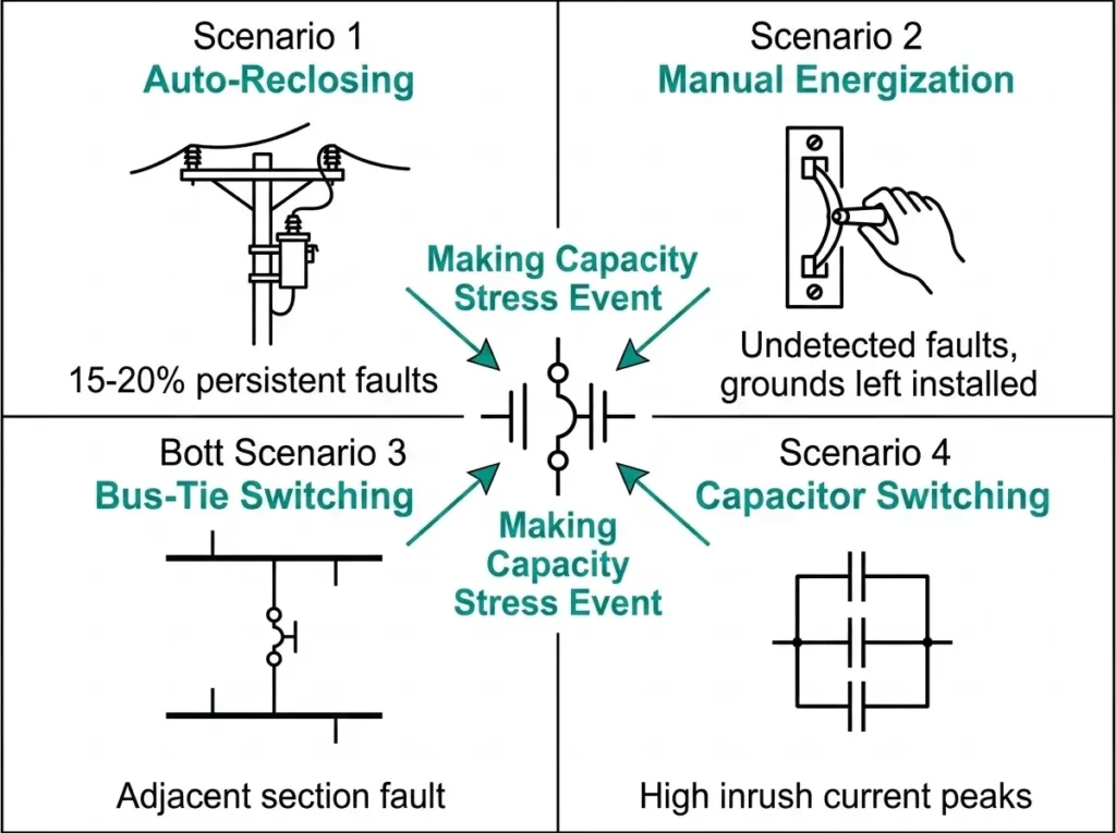
Field experience across 40+ industrial substations reveals that closing-on-fault events, while infrequent, occur predictably in specific operational contexts.
Approximately 80–85% of overhead line faults are transient—cleared by the initial trip. Auto-reclose sequences assume fault clearance. But 15–20% of faults persist. The reclosing breaker closes directly into a sustained fault at full prospective current. Utility feeders experience this regularly over their service life.
Transformers or cables energized with protective grounds mistakenly left installed. Insulation failures that occurred during outage but went undetected before re-energization. Operator error under time pressure to restore service. Human factors drive many closing-on-fault events in industrial settings.
Closing a bus-tie while an undetected fault exists on the adjacent bus section remains a persistent risk. Indoor switchgear installations using ZN85 series breakers in industrial plants face this scenario during load transfers or emergency switching sequences.
Not technically a fault, but inrush peaks can rival or exceed fault levels. Back-to-back capacitor energization produces high-frequency oscillations with extreme peak values that stress making capacity ratings.
A distribution feeder breaker might close onto a fault 2–5 times over a 20-year service life. A main incoming breaker in a critical facility may never experience it—or may face it during the single most consequential switching operation. Specification must address the worst case, not the average.
[Expert Insight: Field Deployment Experience]
- Mining substations with frequent motor starting faults require contact inspection after accumulated making current exposure of 500 kA
- Utility feeders with infrequent faults may operate 15–20 years before reaching similar cumulative stress levels
- Applications with high fault-level proximity—substations fed directly from utility interconnections—demand close-latch verification beyond catalog ratings
- Repeated fault-close operations reduce contact life by 40–60% compared to normal load switching cycles
IEC 62271-100 clause 4.101 defines rated short-circuit making current as the peak value of the first major loop of current the breaker can make at rated voltage. The standard specifies this value in kA peak—never RMS.
The multiplier emerges from fault current theory:
Peak making current derives from ip = √2 × Isc × (1 + e−π/ωτ). For power frequency systems with X/R ratio ≈ 14, this yields a factor of approximately 2.5. Higher X/R installations require 2.6 or 2.7 multipliers.
| System Location | Typical X/R | Multiplier | Example (25 kA Isc) |
|---|---|---|---|
| Distribution feeder | ≤ 14 | 2.5 | 62.5 kA peak |
| Near large transformers | 14–20 | 2.6 | 65 kA peak |
| Generator terminals | > 20 | 2.7 | 67.5 kA peak |
The E2 classification per IEC 62271-100 requires two close-open (CO) operations at rated short-circuit making capacity without maintenance intervention. Test duty T100a confirms contact integrity: close onto 100% rated making current, then break. Post-test inspection verifies no contact welding, no mechanism damage, breaker fully operational.
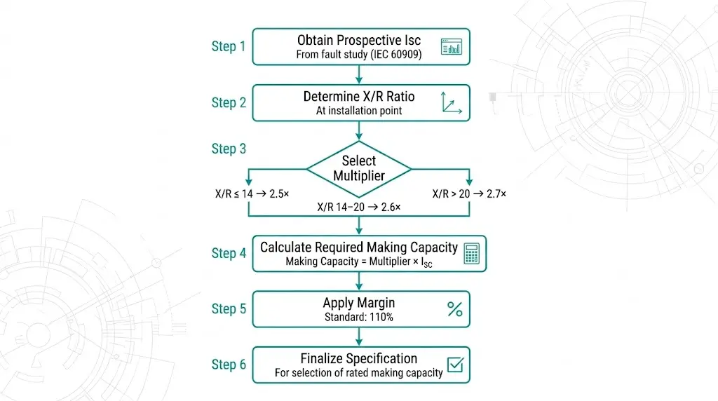
Proper specification prevents the failure mode that breaking capacity alone cannot address. Follow this methodology:
Step 1: Obtain Prospective Short-Circuit Current
Source values from system fault studies per IEC 60909, utility fault current data, or plant electrical studies. Use the value at the breaker installation point. Include planned system growth—additional transformers, parallel sources.
Step 2: Determine System X/R Ratio
Near large transformers or generators: X/R typically exceeds 14. Downstream distribution locations: X/R typically remains at or below 14. If unknown, assume X/R = 14 as the conservative baseline.
Step 3: Select Appropriate Multiplier
Step 4: Calculate Required Making Capacity
Required Making Capacity (kA peak) = Multiplier × Prospective Isc (kA RMS)
Worked example: System Isc = 31.5 kA, X/R = 14 → Making capacity ≥ 2.5 × 31.5 = 78.75 kA peak
Step 5: Apply Margin
Standard practice: specify ≥ 110% of calculated requirement. Critical applications (main incoming, bus-tie): consider 125% margin.
Step 6: Verify on Manufacturer Datasheet
Confirm rated making capacity in kA peak at your system voltage. Some breakers derate at higher voltages within their range.
Sample Specification Statement:
“Vacuum circuit breaker shall have rated short-circuit making capacity of not less than 80 kA peak at 12 kV, tested per IEC 62271-100.”
Common Specification Errors:
Making capacity protects against first-loop mechanical stress during closing-on-fault events. Specify it in kA peak, verify the multiplier matches your system X/R ratio, and confirm the rating on certified datasheets.
XBRELE manufactures medium-voltage vacuum circuit breakers with making capacities from 50 kA to 100 kA peak, fully tested per IEC 62271-100 with certified type test reports. Our application engineering team verifies making capacity requirements against your specific system parameters—fault levels, X/R ratios, and operational profiles.
Contact XBRELE for vacuum circuit breaker quotations with verified making capacity matched to your installation requirements.
Q: What happens if a circuit breaker’s making capacity is exceeded during closing?
Contacts may weld together from localized overheating at microscopic contact points, or the operating mechanism may deform from excessive electromagnetic forces—either condition prevents the breaker from responding to subsequent trip commands.
Q: Why do specifications list making capacity in kA peak while breaking capacity uses kA RMS?
The first half-cycle of fault current contains maximum DC offset, creating an instantaneous peak that determines mechanical stress, whereas breaking capacity reflects the thermal energy of sustained symmetrical current during arc interruption.
Q: How many closing-on-fault events can a vacuum circuit breaker typically withstand?
E2-rated breakers per IEC standards must complete at least two close-open operations at full making capacity without maintenance, though well-designed units often survive 5–10 such events depending on fault magnitude and cumulative I²t exposure.
Q: Does high altitude affect making capacity ratings?
Altitude primarily affects dielectric withstand and breaking performance rather than making capacity directly, though the reduced air density may influence external flashover paths in open-terminal designs above 1,000 meters.
Q: When should I use a 2.6× or 2.7× multiplier instead of the standard 2.5×?
Installations near large generators or bulk power transformers typically exhibit X/R ratios above 14, requiring higher multipliers to account for increased DC offset in the first fault current peak—system fault studies provide the specific X/R values needed.
Q: Can contact wear from normal switching operations reduce making capacity over time?
Contact erosion from routine load switching has minimal impact on making capacity, but accumulated fault-interruption duty and prior closing-on-fault events progressively reduce the contact material available to resist welding during subsequent high-current closing operations.
Q: What distinguishes E1 from E2 making capacity classifications?
E1-rated breakers require maintenance inspection after a single close-open operation at rated making capacity, while E2-rated units must complete two such operations without intervention—E2 is standard for utility and industrial applications where immediate re-energization may be necessary.