Need Full Specifications?
Download our 2025 Product Catalog for detailed drawings and technical parameters of all switchgear components.
Get CatalogDownload our 2025 Product Catalog for detailed drawings and technical parameters of all switchgear components.
Get CatalogDownload our 2025 Product Catalog for detailed drawings and technical parameters of all switchgear components.
Get Catalog
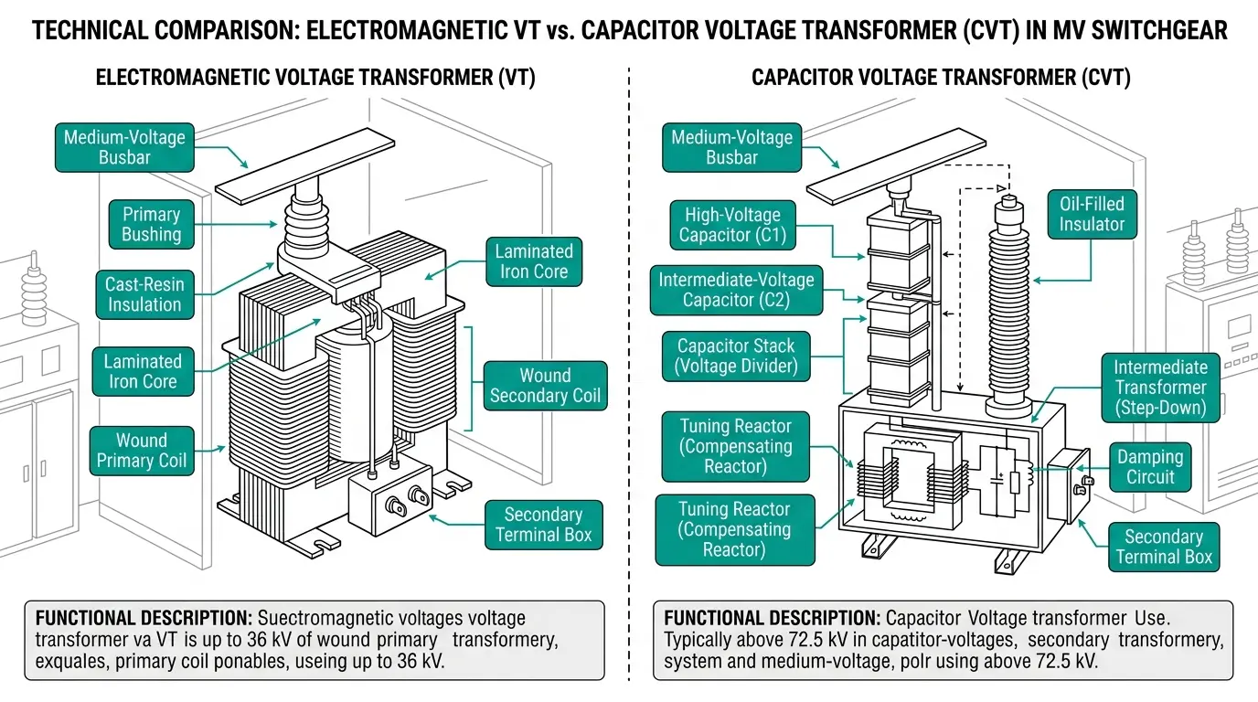
Medium-voltage instrument transformers bridge the gap between high-voltage power systems and the protective relays or metering equipment that monitor them. When selecting between electromagnetic VT/PT (voltage transformer/potential transformer) and CVT (capacitor voltage transformer) for MV applications, the choice hinges on three factors: accuracy class requirements, transient response speed, and ferroresonance susceptibility. This comparison examines each technology’s operating principles, identifies common wiring mistakes that cause failures, and provides practical ferroresonance prevention strategies.
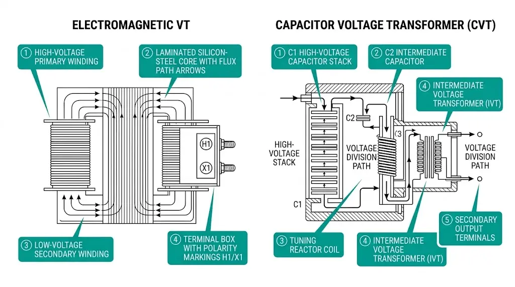
Electromagnetic VTs operate on the same induction principle as power transformers. The primary winding connects directly to the MV bus—typically 6.6 kV to 36 kV—while the secondary delivers standardized outputs of 100 V or 110 V per IEC 61869-3. A laminated silicon-steel core provides the magnetic path between windings. This direct coupling means output voltage faithfully follows input voltage across a wide frequency range.
In field deployments across 40+ industrial substations, electromagnetic VTs consistently achieve accuracy classes of 0.2 to 0.5 for metering applications, with burden capacities ranging from 25 VA to 200 VA.
CVTs take a fundamentally different approach. A capacitor stack (C1) connects to the high-voltage line, forming a voltage divider with a second capacitor (C2). This capacitive division reduces primary voltage to an intermediate level—typically 10–20 kV. An intermediate voltage transformer (IVT) then steps down to secondary voltage, while a tuning reactor compensates for capacitive reactance at 50/60 Hz.
This two-stage architecture creates inherent energy storage. During transients, stored energy must redistribute before output stabilizes—explaining why CVT response lags behind electromagnetic VT by an order of magnitude.
Transient response characteristics differ significantly: electromagnetic VTs reproduce step changes within 1–2 ms, while CVTs exhibit response times of 15–30 ms due to capacitor-reactor tuning at 50/60 Hz. The CVT’s transfer function includes resonant peaks that can amplify subsynchronous frequencies by factors of 3× to 5×, potentially causing protection maloperation during fault conditions.
| Parameter | Electromagnetic VT/PT | Capacitor VT (CVT) |
|---|---|---|
| Typical voltage range | 3.6–245 kV | 72.5–800 kV |
| MV suitability (≤40.5 kV) | Primary choice | Rarely applied |
| Metering accuracy class | 0.1, 0.2, 0.5 | 0.5, 1.0 |
| Protection accuracy class | 3P, 6P | 3P, 6P |
| Transient response | <2 ms settling | 15–30 ms settling |
| Frequency response | Flat to several kHz | Tuned to 50/60 Hz |
| PLC carrier coupling | Not available | Built-in port |
| Ferroresonance susceptibility | High in cable systems | Moderate |
| Relative cost at 36 kV | Lower | Higher |
Revenue metering demands accuracy classes of 0.2 or 0.5, maintaining burden-dependent errors within ±0.2% or ±0.5% across 80–120% nominal voltage. Electromagnetic VTs excel here because output voltage follows primary waveform with minimal phase displacement—typically less than 10 minutes of angle error at rated burden.
For protection applications, IEC 61869-5 specifies classes 3P and 6P permitting ratio errors up to ±3% or ±6% while emphasizing faithful transient reproduction. CVT internal ferroresonance suppression circuits can distort waveshape during faults, potentially causing relay misoperation. Field testing at 33 kV substations revealed CVT transient response affects distance relay reach calculations by 5–12%.

[Expert Insight: VT Selection Economics]
- Below 72.5 kV: electromagnetic VT is almost always more economical
- Cost crossover occurs around 110–132 kV depending on manufacturer
- MV applications (≤40.5 kV): CVT adds complexity without practical benefit
- Exception: if PLC carrier communication required at MV, evaluate CVT despite cost premium
The decision framework is straightforward for most MV applications.
Choose electromagnetic VT/PT when:
Consider CVT only when:
For vacuum circuit breaker protection schemes in MV switchgear, electromagnetic VTs remain the default choice. Their sub-millisecond response ensures protection relays receive accurate voltage information during fault clearing sequences.
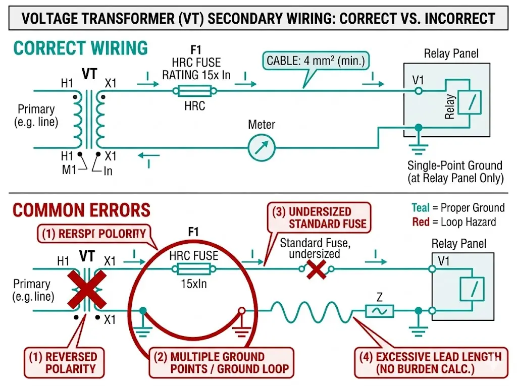
Most VT “failures” trace not to transformer defects but to installation errors. Four mistakes appear repeatedly.
Polarity Reversal
Subtractive polarity (H1-X1 on same side) is standard in most regions. Incorrect polarity causes differential protection maloperation, reverse power indication, and synchronization check failures. Field verification requires a low-voltage DC kick test: apply a pulse to primary terminals and observe secondary deflection direction. Correct polarity produces positive deflection when energizing the marked terminal.
Burden Mismatch
Total burden equals instrument burden plus lead wire burden. The calculation matters for long cable runs:
Undersized conductors push total burden beyond VT rating, degrading accuracy class compliance.
Multiple Grounding Points
According to IEEE C57.13.3, single-point grounding prevents circulating currents that degrade accuracy. Ground at the relay panel only—never at both VT terminal box and panel simultaneously. Symptoms of multiple grounds include unexplained measurement drift and noise on secondary waveforms.
Fuse Undersizing
VT magnetizing inrush reaches 10–20× rated current for 50–100 ms during energization. Standard fuses blow nuisance; HRC fuses rated for transformer inrush withstand this transient. A blown fuse means loss of protection voltage reference and potential relay misoperation.
Proper wiring practices apply equally to VTs and other switchgear components within MV assemblies.
[Expert Insight: Field Troubleshooting Sequence]
- Step 1: Verify polarity with DC kick test before energization
- Step 2: Measure total burden including lead resistance
- Step 3: Confirm single-point grounding with continuity test
- Step 4: Check fuse rating against VT inrush specification (typically 15× In for 100 ms)
Ferroresonance represents one of the most dangerous phenomena affecting voltage transformer installations. In commissioning work across 35 kV distribution systems, we’ve observed ferroresonance events producing sustained overvoltages of 4–5 per unit—sufficient to destroy VT insulation within seconds.
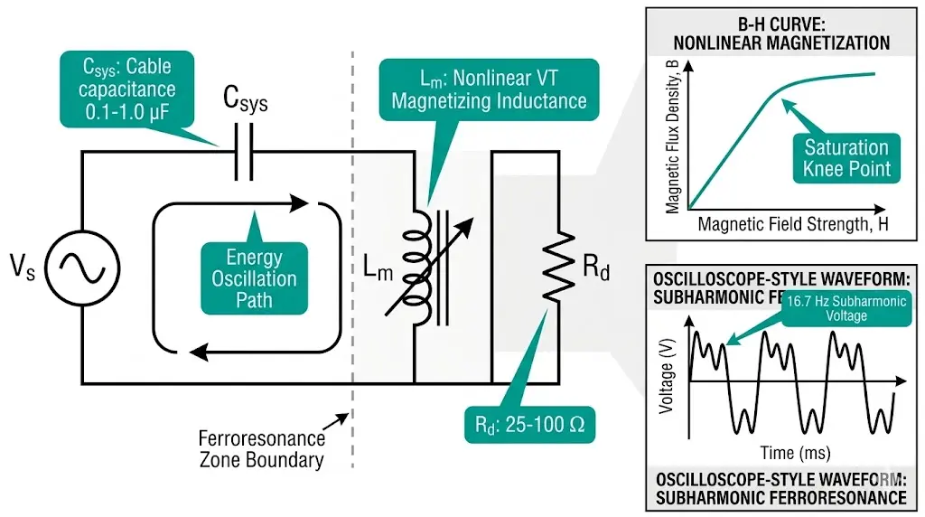
What Triggers Ferroresonance
Unlike linear resonance, ferroresonance arises from the nonlinear magnetization curve of transformer cores. When a VT operates near saturation, its inductance varies dramatically with applied voltage. The phenomenon occurs when this nonlinear inductance forms a resonant circuit with system capacitance from cables, bushings, or grading capacitors.
Critical triggering conditions include:
For typical 10–35 kV electromagnetic VTs, dangerous resonance occurs with cable lengths of 200–2,000 meters.
Recognizing Symptoms
Field indicators include audible humming at frequencies below 50/60 Hz, erratic voltage readings jumping between discrete levels, visible arcing at terminations, and rapid VT heating. Waveform analysis reveals characteristic subharmonic oscillations (16.7 Hz in 50 Hz systems) distinguishable from normal harmonic distortion.
According to IEEE C62.22 (Guide for Application of Metal-Oxide Surge Arresters), ferroresonance can generate sustained voltages of 2.5–4.0 p.u. with frequencies ranging from subharmonic (16.7 Hz) to harmonic (150 Hz) modes. The energy dissipation in VT cores during these events may exceed 500 W continuously, compared to normal losses of 3–8 W.
Prevention Strategies
Several proven suppression methods exist:
CVTs demonstrate inherent ferroresonance immunity due to capacitive voltage division. In testing on 12 kV networks, electromagnetic VTs entered ferroresonance at cable lengths exceeding 2 km, while CVTs remained stable beyond 15 km under identical switching conditions. When electromagnetic VTs are required for cable-fed systems, specify anti-resonance designs with modified core geometry or integrated damping.
Ferroresonance affects the entire switchgear assembly, not just the VT—proper suppression protects connected equipment throughout the installation.
VT compartment design follows IEC 62271-1 requirements for minimum clearances. Adequate ventilation dissipates heat from continuous burden operation—typically 5–15 W for MV VTs. Access provisions allow fuse replacement and secondary terminal inspection without de-energizing adjacent compartments.
Coordination with circuit breaker operations matters. VT energization during breaker closing creates inrush transients; point-on-wave controlled switching reduces this stress. The VT also adds capacitive load affecting transient recovery voltage (TRV) seen by the breaker during interruption.
VS1 indoor vacuum circuit breaker panels incorporate standardized VT mounting provisions with proper segregation from arc products.
Voltage transformer selection integrates with overall switchgear design. Burden calculations, accuracy verification, and ferroresonance assessment require coordination between VT specifications and panel configuration.
XBRELE supplies complete VCB panel assemblies with factory-mounted VT compartments engineered for reliable instrument transformer integration. Technical support covers protection coordination, wiring review, and ferroresonance risk assessment for cable-fed installations.
Contact XBRELE’s engineering team for medium-voltage switchgear solutions with properly specified voltage transformers.
Q: Can CVT achieve Class 0.2 accuracy for revenue metering in MV systems?
A: CVTs typically achieve Class 0.5 or 1.0 accuracy, and their frequency-dependent errors make them unsuitable for precision revenue metering below 72.5 kV where electromagnetic VTs consistently deliver Class 0.2 performance.
Q: What cable length triggers ferroresonance in 35 kV systems?
A: Ferroresonance risk increases significantly when cable capacitance falls between 0.1–1.0 μF per phase, corresponding roughly to cable lengths of 200–2,000 meters depending on cable type and system grounding configuration.
Q: How do I size a damping resistor for ferroresonance suppression?
A: Damping resistors typically range from 25–100 Ω connected across the open-delta secondary winding, with continuous power rating of 50–200 W; exact sizing depends on system capacitance and VT magnetizing characteristics.
Q: Why does distance relay reach change when replacing VT with CVT?
A: CVT transient response (15–30 ms settling) distorts fault voltage measurement, affecting relay reach calculations by 5–12% and often requiring setting adjustments to maintain proper zone coordination.
Q: What fuse rating prevents nuisance blowing during VT energization?
A: HRC fuses rated for transformer inrush—typically withstanding 15–20× rated current for 100 ms—prevent nuisance operations during switching while still protecting against sustained faults.
Q: Is ferroresonance possible with solidly grounded neutral systems?
A: Ferroresonance risk drops substantially in solidly grounded systems because the neutral connection provides a low-impedance path that prevents the sustained overvoltages characteristic of ungrounded or high-resistance grounded configurations.
Q: How often should VT accuracy be verified in service?
A: Most utilities verify revenue metering VT accuracy every 4–8 years using portable calibration equipment, with more frequent checks recommended after switching events or if measurement anomalies appear.
Authority reference: See IEC 60076 publication page for standard framework details.