Need Full Specifications?
Download our 2025 Product Catalog for detailed drawings and technical parameters of all switchgear components.
Get CatalogDownload our 2025 Product Catalog for detailed drawings and technical parameters of all switchgear components.
Get CatalogDownload our 2025 Product Catalog for detailed drawings and technical parameters of all switchgear components.
Get Catalog
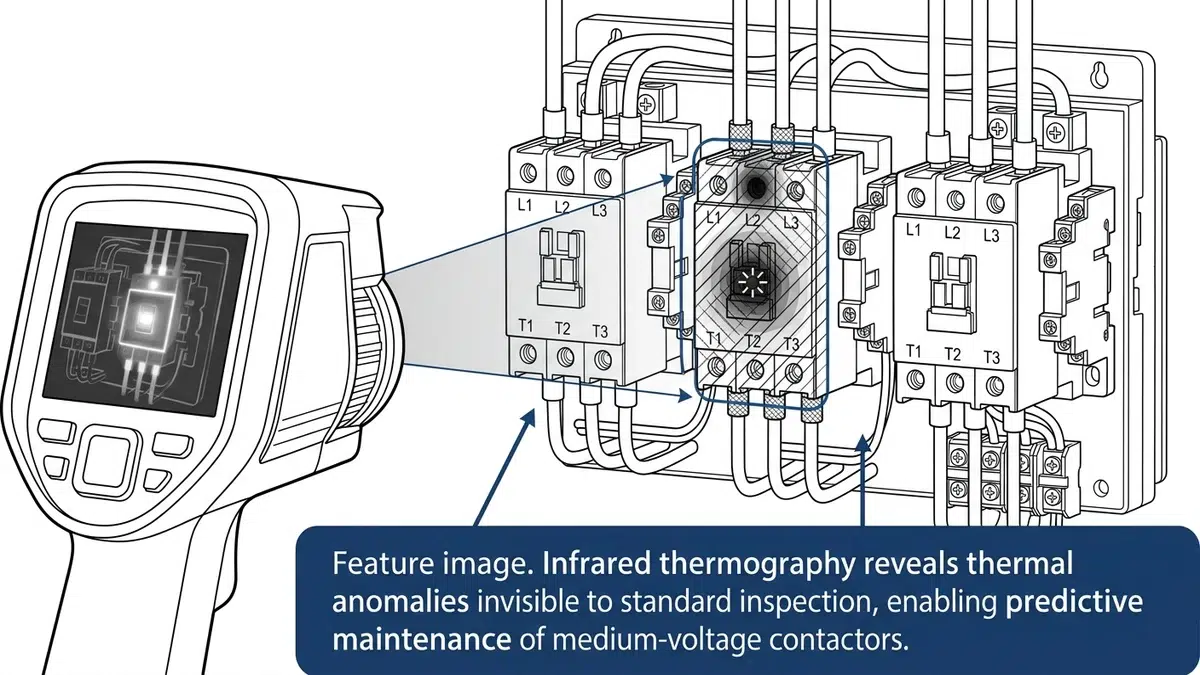
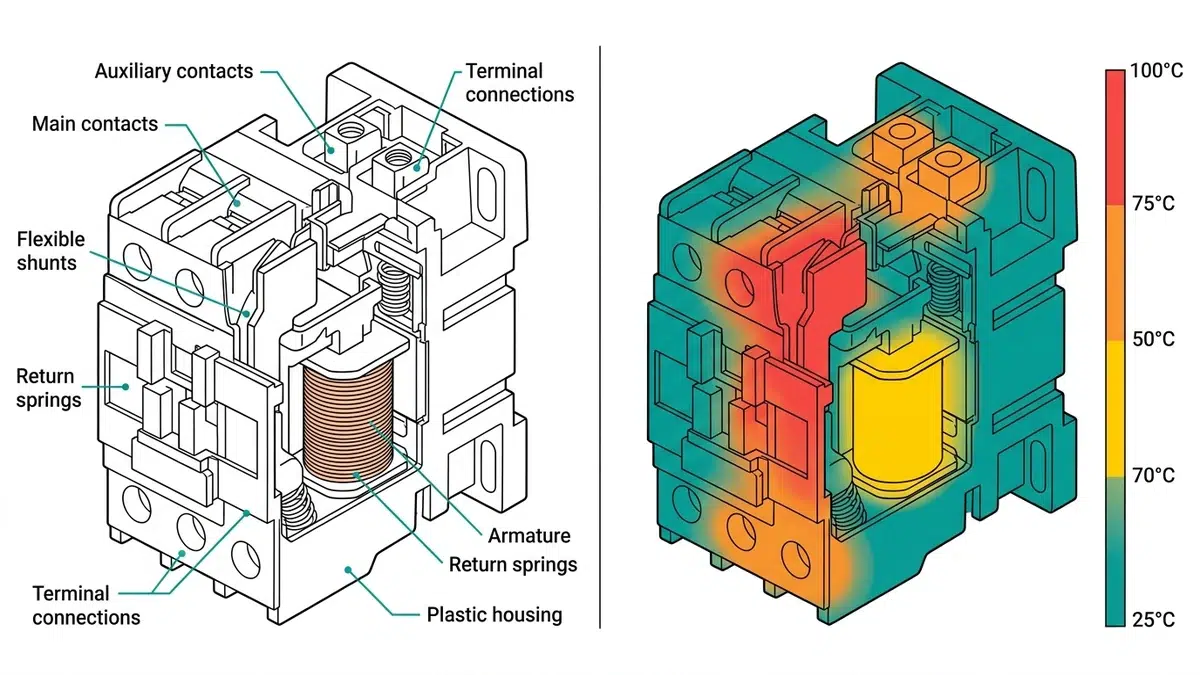
Infrared thermography for contactors detects thermal anomalies before they escalate into failures. By capturing surface temperature variations caused by resistance changes, loose connections, or deteriorating contact surfaces, this non-invasive diagnostic method transforms invisible electrical problems into actionable maintenance intelligence.
In field assessments across 200+ industrial motor control centers, we consistently observe that healthy contactors maintain contact temperatures within 10–15°C above ambient during rated load operation. Hot-spots exceeding this differential signal resistance increases at connection interfaces, contact wear, or internal conductor degradation requiring investigation.
Hot-spot formation follows predictable heat generation physics governed by Joule heating principles. Three primary mechanisms produce distinct thermal signatures: increased contact resistance at terminal connections, conductor-to-lug interface degradation, and internal contact wear within the switching chamber.
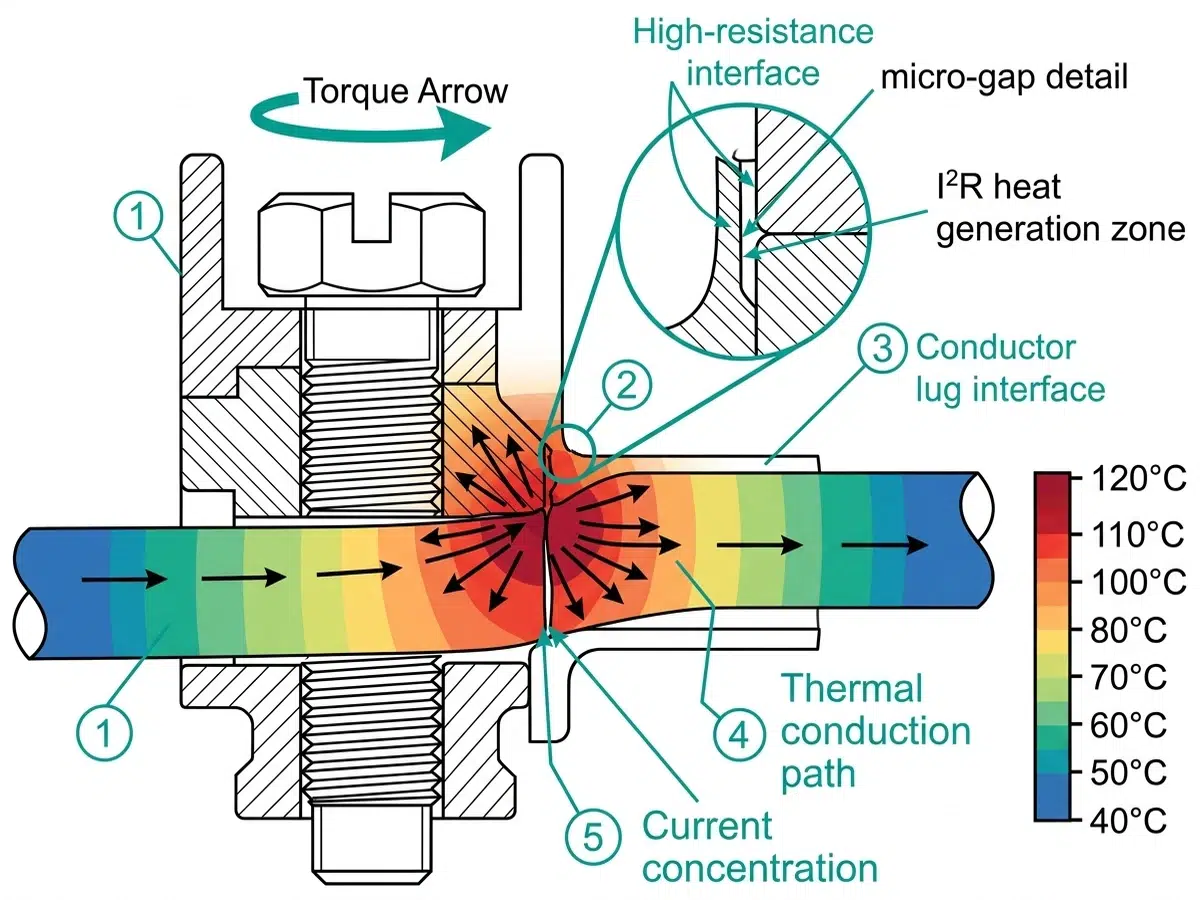
Contact Resistance and Heat Generation
The fundamental physics follows Joule’s law—heat generation is directly proportional to contact resistance and the square of current flow.
Heat generated (P) = I² × R, where contact resistance values exceeding 100 μΩ typically indicate developing problems. For a contactor carrying 400 A, a resistance increase from 50 μΩ to 200 μΩ raises power dissipation from 8 W to 32 W at the connection point—a fourfold increase concentrated in a small area.
Progressive Degradation Patterns
Contact degradation follows a non-linear progression. Initial oxidation at copper or silver-alloy contact surfaces creates thin resistive films measuring 0.1–0.5 μm thick. These films increase local resistance, generating heat that accelerates further oxidation—a self-reinforcing cycle that explains why contactors can operate acceptably for years, then deteriorate rapidly once a threshold is crossed.
Field data from mining and petrochemical facilities reveals that loose terminal connections account for approximately 60% of contactor hot spots, while internal contact wear represents 25% of thermal anomalies detected during routine IR surveys.
[Expert Insight: Field Observations on Hot-Spot Development]
– Contactors in high-vibration environments (crushers, conveyors) develop terminal loosening 3× faster than static installations
– Silver-plated contacts mask early degradation—resistance increases significantly before visible pitting appears
– Thermal anomalies typically precede mechanical failure by 3–6 months if load patterns remain constant
– Morning scans often miss intermittent problems; scan during peak production load for reliable detection
Modern thermal cameras for electrical maintenance offer thermal sensitivity (NETD) of 50 mK or better, enabling detection of temperature differentials as small as 0.05°C. For vacuum contactor diagnostics, cameras with resolution of 320 × 240 pixels or higher adequately capture thermal gradients across typical 45–95 mm frame sizes.
Thermal Emission Principles
Every contactor component emits infrared radiation according to its surface temperature and emissivity coefficient. The relationship is non-linear.
The Stefan-Boltzmann relationship governs radiant heat emission: total radiated power increases proportionally to T4 (temperature to the fourth power). This non-linear relationship means a contactor operating at 85°C emits approximately 40% more infrared energy than one at 60°C, making thermal anomalies progressively easier to detect as severity increases.
Emissivity Compensation Requirements
Copper contact surfaces typically exhibit emissivity values between 0.60 and 0.85, depending on oxidation level and surface condition. Oxidized or pitted contacts demonstrate higher emissivity values, which paradoxically can improve detection accuracy while simultaneously indicating degraded contact integrity.
| Material | Emissivity (ε) | Notes |
|---|---|---|
| Oxidized copper | 0.65–0.78 | Most terminal surfaces |
| Bare polished copper | 0.02–0.07 | Unreliable for direct IR reading |
| Silver-plated contact | 0.02–0.05 | Use reference method |
| Painted steel enclosure | 0.90–0.95 | Good measurement surface |
| Epoxy/resin insulation | 0.85–0.92 | Reliable reference point |
For low-emissivity surfaces, apply electrical tape reference patches or use the comparative ΔT method—measuring phase-to-phase differences rather than absolute temperatures eliminates emissivity uncertainty.
Each thermal anomaly pattern corresponds to specific degradation mechanisms. Understanding these relationships enables targeted maintenance rather than wholesale replacement.
Main Contact Zone Patterns
Elevated temperatures at the main contact interface indicate contact erosion and contamination. Main contact hot spots typically reflect resistance increases of 50–150% above baseline. The physics mechanism involves reduced contact area as silver-alloy surfaces erode through arcing cycles, concentrating current flow through smaller conductive patches.
Hot spots at main contacts present as symmetric thermal patterns across all three phases when wear is uniform, or asymmetric when one pole experiences accelerated degradation.
Terminal Connection Anomalies
Terminal hot spots reveal loose connections or conductor degradation at the junction between incoming/outgoing conductors and contactor terminals. Field experience shows that terminal temperatures exceeding 40°C above ambient frequently correlate with torque values below 60% of specification.
The thermal signature differs distinctly: terminal hot spots show gradual temperature gradients extending along conductors, while contact zone heating remains localized within the contactor housing.
Coil and Magnetic Circuit Heating
Elevated coil temperatures or warmth around the magnetic circuit indicate coil insulation degradation, shorted turns, or mechanical binding causing extended inrush periods. Coil temperatures consistently above 85°C suggest imminent failure within 3–6 months under normal duty cycles.
| Hot-Spot Location | Probable Cause | Verification Step |
|---|---|---|
| Single main terminal | Loose hardware, oxidized interface | Torque check, contact resistance test |
| Flexible shunt/braid | Fractured strands, corrosion | Visual inspection, continuity test |
| One phase elevated (balanced load) | Asymmetric contact wear | Contact resistance comparison across phases |
| Enclosure near interrupter | Internal contact degradation | Contact resistance measurement |
| Control terminal | Loose screw, undersized wire | Torque check, wire gauge verification |
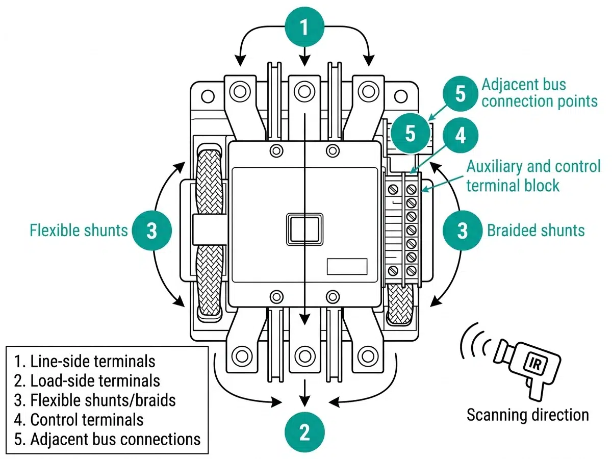
For enclosed designs like the CKG series vacuum contactor, external terminal measurement remains the only option—internal contact conditions must be inferred from terminal temperature rise patterns.
[Expert Insight: Pattern Recognition from 10+ Years of Industrial Surveys]
– Phase-to-phase temperature difference >15°C under balanced load always warrants investigation—even if absolute temperatures seem acceptable
– Sudden ΔT increase (>5°C between surveys under similar conditions) signals accelerated wear; advance the maintenance schedule immediately
– Thermal anomalies at contact system components often correlate with audible buzzing or visible arc flash residue on enclosure vents
– Document load current at scan time—findings are meaningless without this context
Systematic scanning ensures no thermal anomaly escapes detection. Before scanning, verify that contactors carry at least 40% of rated current for a minimum of 30 minutes—thermal signatures from developing faults require adequate heat buildup to manifest.
Pre-Scan Checklist
Five-Zone Scanning Sequence
Capture both absolute temperature and ΔT relative to a similar component. The coolest phase in a three-phase bank typically serves as the reference baseline. Always record load current at scan time—a thermal finding at 60% load represents a more serious condition than the same reading at 100% load.
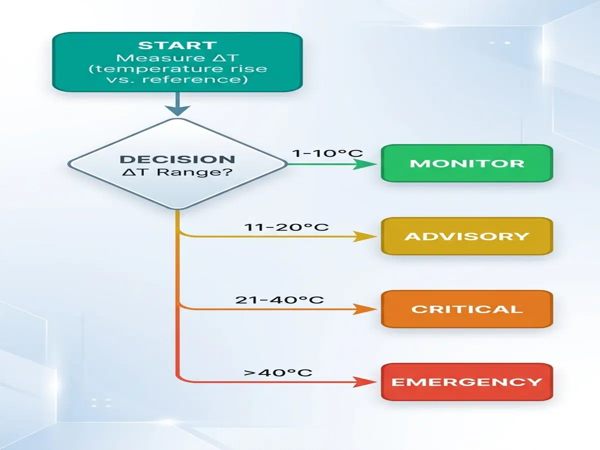
Temperature readings translate into maintenance decisions through a severity classification framework. The temperature-rise method provides more reliable assessment than absolute temperature readings alone.
A contactor terminal measuring 85°C in a 40°C ambient represents a 45°C rise—more concerning than a 95°C reading in a 65°C foundry environment showing only 30°C rise. According to NETA MTS-2019 (Maintenance Testing Specifications), thermographic surveys should identify temperature rises exceeding 10°C above reference as requiring investigation.
Level 1 (Monitor): ΔT = 1–10°C above reference. Schedule inspection within 90 days. Typical causes include minor contact oxidation or slight torque relaxation.
Level 2 (Priority): ΔT = 11–25°C above reference. Schedule repair within 30 days. Common issues involve progressive contact wear or loose terminal connections requiring re-torquing to manufacturer specifications (typically 2.5–4.0 N·m for control terminals).
Level 3 (Serious): ΔT = 26–40°C above reference. Schedule repair within 7 days. Indicates significant contact degradation, phase imbalance exceeding 10%, or internal connection failure.
Level 4 (Critical): ΔT > 40°C above reference. Immediate action required—reduce load or isolate circuit. Risk of insulation failure, contact welding, or fire exists at this severity.
| Severity | ΔT Above Reference | Timeline | Action Required |
|---|---|---|---|
| Monitor | 1–10°C | 90 days | Document, verify at next outage |
| Priority | 11–25°C | 30 days | Re-torque, clean contacts |
| Serious | 26–40°C | 7 days | Prepare parts, schedule repair |
| Critical | >40°C | Immediate | Load reduction or isolation |
Load Compensation Factor
A contactor operating at 50% rated current generates approximately 25% of full-load heating (following I²R relationships). Normalize thermal findings to full-load equivalent temperatures before applying threshold criteria. This ensures consistent severity classification regardless of when measurements are taken.
According to IEC 62271-106, temperature rise limits for current-carrying contacts should not exceed 65 K above ambient for silver-plated surfaces under rated continuous current. This provides the baseline for thermographic assessment.
Tiered Response Protocol
Level 1–2 Findings: Document thermal image with timestamp and load data. Schedule connection torque verification at next planned outage. Re-scan at standard interval (typically 6–12 months for industrial applications).
Level 3 Findings: Plan maintenance within 7 days maximum. De-energize, clean contact surfaces, re-torque to specification. Inspect flexible connectors for strand breakage or discoloration. Perform contact resistance measurement before and after repair. Re-scan after correction to verify resolution.
Level 4 Findings: Immediate response required. Options include emergency load transfer, controlled shutdown, or continuous monitoring if shutdown is impossible. Full disassembly inspection with contact replacement and connection rebuild. Conduct root cause analysis to prevent recurrence.
Documentation Requirements
Every thermal survey report should include:
– Thermal image with calibrated temperature scale
– Corresponding visual photograph
– Equipment identification (panel ID, cubicle number, contactor designation)
– Load current at time of scan
– Ambient temperature
– ΔT calculation (vs. reference and vs. ambient)
– Severity classification
– Recommended action and priority level
Maintain minimum 3 years of thermal history for trend analysis. Compare identical measurement points across survey intervals. Plot ΔT progression over time to identify degradation rates and predict replacement timing.
Thermal reliability begins at the design stage. Contactors engineered with optimized contact geometry, high-conductivity flexible shunts, and robust terminal designs present fewer hot-spot problems throughout their service life.
XBRELE vacuum contactors feature silver-alloy main contacts sized for low current density, flexible copper shunts rated for mechanical cycling without strand fatigue, and terminal designs that maintain torque retention under thermal cycling. For applications where thermal performance and long-term reliability matter, consult with an experienced vacuum contactor manufacturer during the specification phase.
\n
Contactors should carry at least 40% of rated current for a minimum of 30 minutes before scanning; lower loads may not generate sufficient heat to reveal developing thermal anomalies.
\n
Apply electrical tape reference patches to create a known-emissivity surface, or use the comparative ΔT method measuring phase-to-phase differences rather than absolute temperatures.
\n
External terminal measurements can infer internal contact degradation—elevated terminal temperatures without visible external causes often indicate internal contact wear requiring contact resistance verification.
\n
Annual surveys suit most industrial applications; high-duty contactors exceeding 50,000 operations annually or those in critical processes may warrant semi-annual scanning.
\n
Temperature rises exceeding 40°C above a comparable reference component indicate critical conditions requiring action within 24–72 hours, including possible load reduction or controlled shutdown.
\n
Phase-to-phase temperature differences under balanced load typically indicate uneven contact wear, different terminal torque values, or conductor sizing variations—differences exceeding 15°C warrant investigation regardless of absolute temperature.
\n
Either approach is valid, but the configuration must be documented and kept consistent across surveys; open doors improve camera access but alter convection patterns affecting temperature readings.