Need Full Specifications?
Download our 2025 Product Catalog for detailed drawings and technical parameters of all switchgear components.
Get CatalogDownload our 2025 Product Catalog for detailed drawings and technical parameters of all switchgear components.
Get CatalogDownload our 2025 Product Catalog for detailed drawings and technical parameters of all switchgear components.
Get Catalog
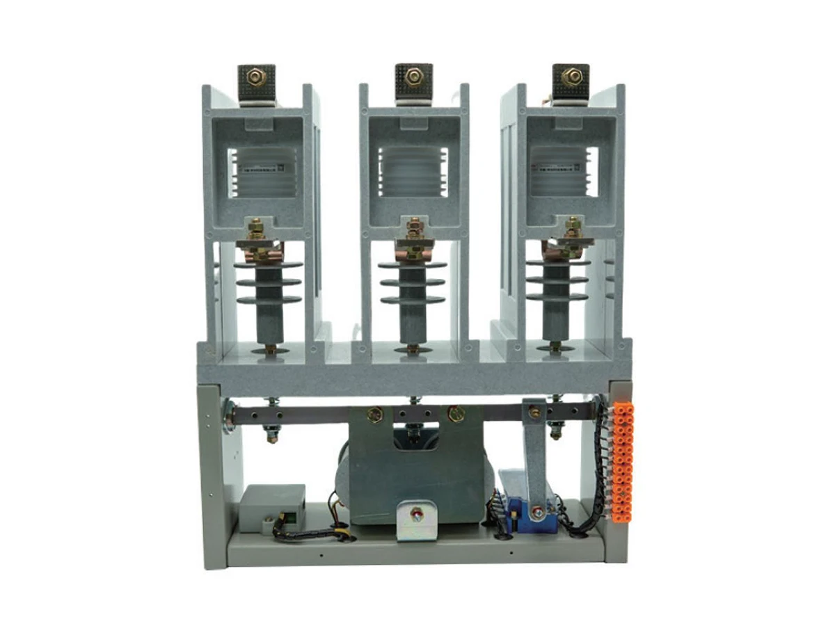
XBRELE CKG vacuum contactor series is developed for medium voltage motor, transformer and capacitor bank applications. CKG3-7.2 and CKG4-12 contactors offer reliable vacuum interruption, compact construction and flexible control circuits, making them suitable for OEM switchgear panels and retrofit projects in 7.2 kV and 12 kV distribution networks.
The CKG vacuum contactor series covers CKG3-7.2 and CKG4-12 models designed for medium voltage motor, transformer and capacitor bank switching. Each unit adopts a compact vacuum interrupter assembly combined with reliable electromagnetic or permanent-magnet operating mechanisms, suitable for frequent duty cycles in OEM switchgear and industrial distribution systems.
The interrupter and arc-quenching components are arranged to provide stable dielectric performance under repeated operations, while coil options (AC/DC) give panel builders flexibility for control circuit design. Rated currents extend from standard 400–630A units up to 800A, 1000A and 1250A high-current versions in the CKG4 range, meeting different feeder and motor-starting requirements.
Specialized variants such as CKG4-1600/12, CKG4-2000/12, capacitor-switching models and mechanical interlocking configurations give EPC integrators a unified family platform for diverse MV applications. Installation and maintenance follow standard indoor panel practices, ensuring consistent performance across long-term operation.
For a broader view of XBRELE’s medium-voltage switching portfolio, please visit the Vacuum Contactor pillar page .
Select a series below to view representative product photos, key electrical ratings and outline & mounting dimensions for engineering design and switchgear layout.
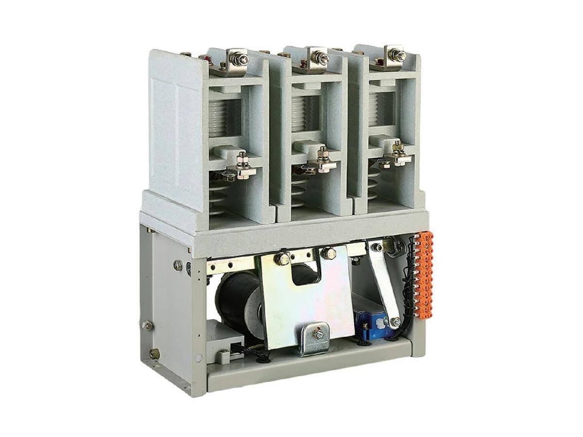
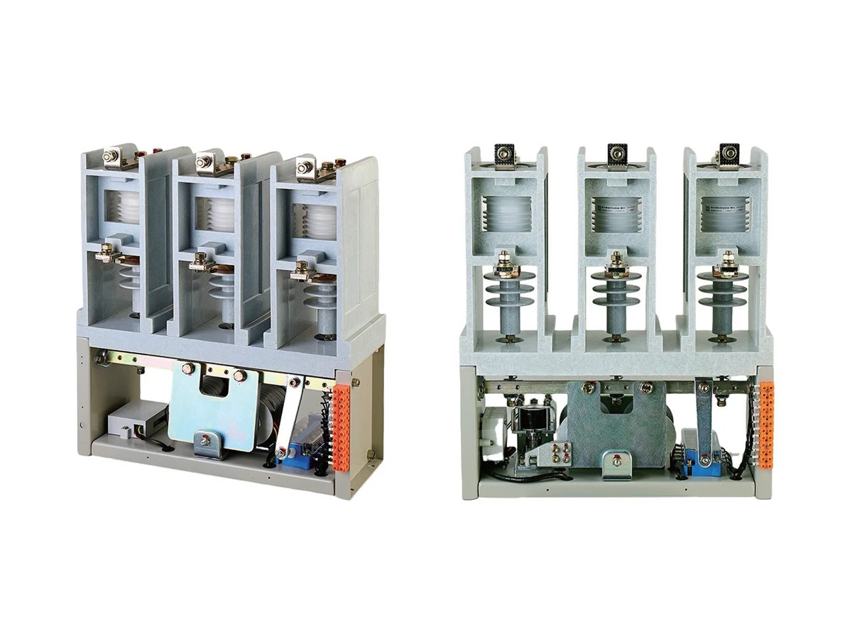
CKG3 7.2 kV vacuum contactors are used in indoor MV switchgear and control equipment with AC 50 Hz, rated voltage up to 7.2 kV and rated current up to 630 A. They are suitable for frequent switching of motors, transformers and capacitor banks in power systems.
The series adopts a reliable vacuum interrupter and operating mechanism with compact structure, fast making and breaking, high dielectric strength and long mechanical & electrical life. In the CKG3-□/7.2F□□ variant, the main circuit and contacts are optimised for back-to-back capacitor bank switching.
The table below summarises the main electrical ratings for the CKG3-□/7.2 and CKG3-□/7.2F□□ vacuum contactors. Items marked “(F□□ only)” apply only to the back-to-back capacitor switching type.
Main technical parameters — CKG3 7.2 kV series
Ratings for CKG3-□/7.2 standard and CKG3-□/7.2F□□ back-to-back capacitor switching vacuum contactors.
| No. | Item | Unit | Parameter |
|---|---|---|---|
| 1 | Rated voltage | kV | 7.2 |
| 2 | Rated current | A | 160, 250, 400, 630 |
| 3 | Power-frequency withstand voltage (1 min) | kV | 32 |
| 4 | Lightning impulse withstand voltage | kV | 60 |
| 5 | Rated short-time withstand current | kA | 10 |
| 6 | Rated peak withstand current | kA | 25 |
| 7 | Overload withstand current | kA | 15 |
| 8 | Rated breaking capacity (AC-3 duty) | A | 8 × Ie, 25 operations |
| 9 | Rated making capacity (AC-3 duty) | A | 10 × Ie, 100 operations |
| 10 | Individual capacitor breaking current (F□□ only) | A | 100 / 200 / 300 |
| 11 | Back-to-back capacitor bank breaking current (F□□ only) | A | 80 / 160 / 200 |
| 12 | Rated contact gap | mm | 4 ± 0.5 (6 ± 0.5 for F□□) |
| 13 | Overtravel | mm | ≥ 1.5 |
| 14 | Simultaneity of poles | ms | ≤ 2 |
| 15 | Electrical life (AC-3 duty) | Operations (×104) | 25 |
| 16 | Electrical life (AC-4 duty) | Operations (×104) | 10 |
| 17 | Mechanical life | Operations (×104) | 50 |
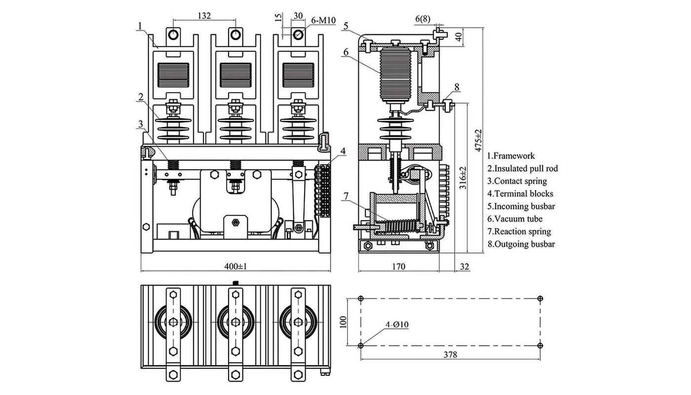
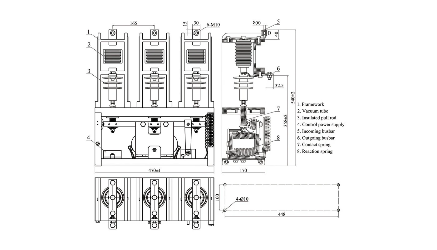
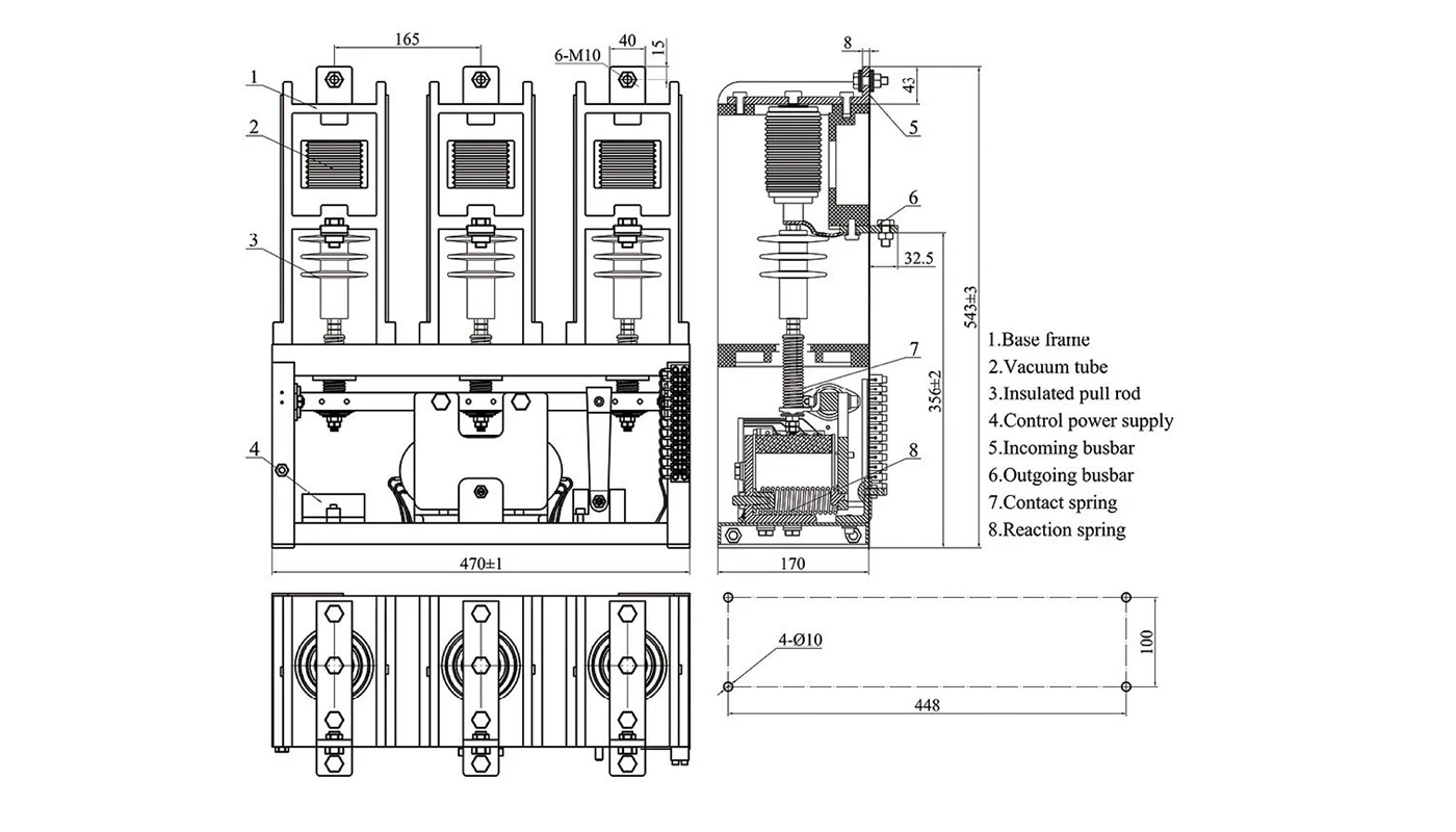
Outline & mounting dimensions — CKG3-□/7.2 & CKG3-□/7.2F□□
Typical outline and mounting dimensions for the standard CKG3-□/7.2 indoor vacuum contactor and the CKG3-□/7.2F□□ back-to-back capacitor switching type. Use these drawings for cabinet layout and busbar connection design, and verify all key dimensions against the latest XBRELE engineering documents.
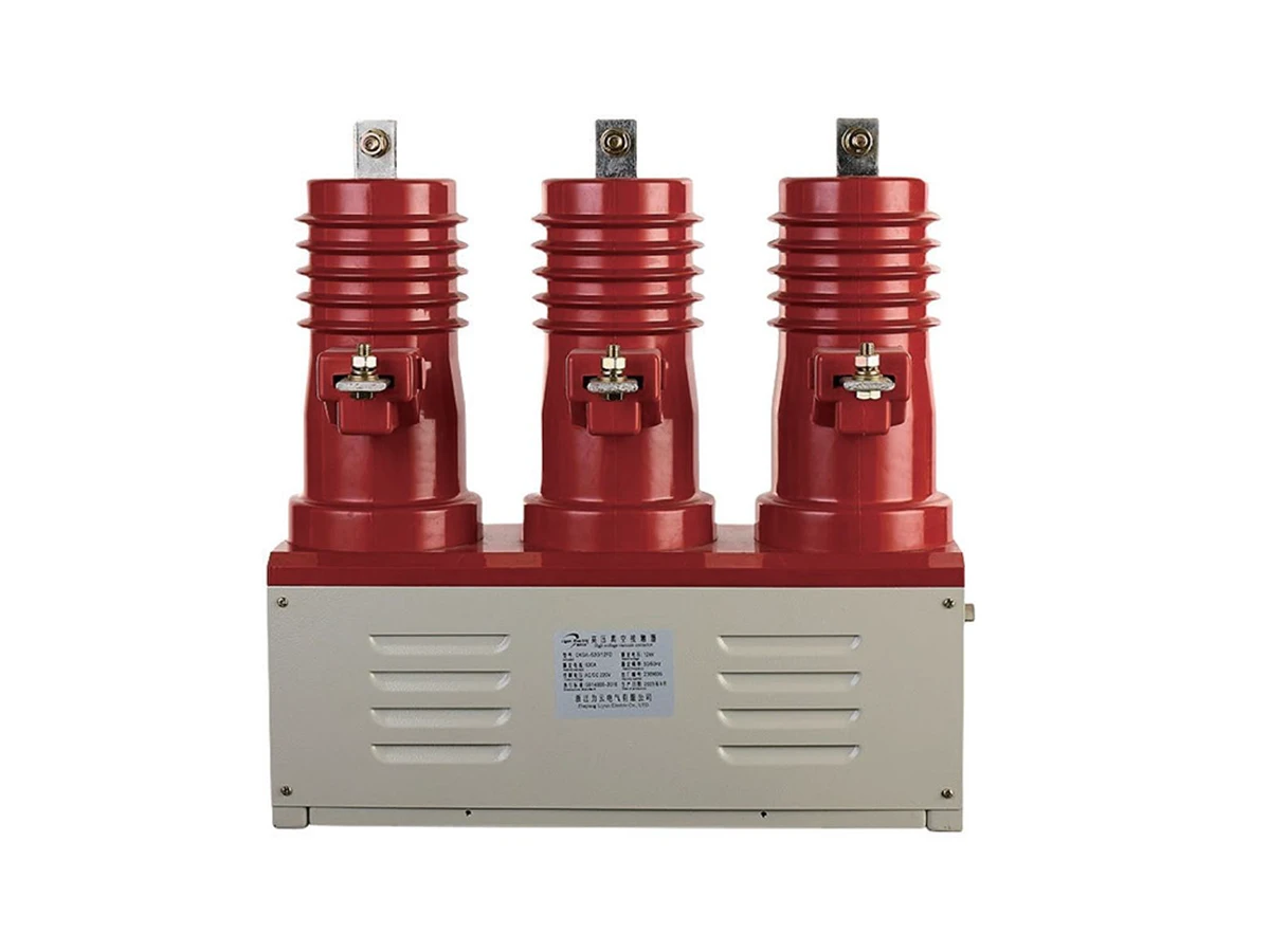
The CKG4 12 kV family covers standard feeder duty, permanent magnet types and back-to-back capacitor bank switching designs. All models are suitable for indoor metal-clad switchgear with AC 50 Hz systems, rated voltage 12 kV and rated current up to 630 A.
CKG4-□/12FD is mainly used for motor and feeder switching. CKG4-□/12FC adopts a permanent magnet operating mechanism with fast speed and stable holding force. CKG4-□/12F□B□□ is specially designed for individual and back-to-back capacitor banks, with optimised contact structure and current-limiting performance.
The combined data table below compares the main electrical ratings of CKG4-□/12FD, CKG4-□/12FC and CKG4-□/12F□B□□ so that engineers can quickly choose the right type for each feeder or capacitor bank.
Main technical parameters — CKG4-□/12FD / CKG4-□/12FC / CKG4-□/12F□B□□
Comparative ratings for standard feeder type, permanent magnet type and back-to-back capacitor switching type. Values should be checked against the latest XBRELE datasheets before final design.
| No. | Item | Unit | CKG4-□/12FD | CKG4-□/12FC | CKG4-□/12F□B□□ |
|---|---|---|---|---|---|
| 1 | Rated voltage | kV | 12 | 12 | 12 |
| 2 | Rated current | A | 160 / 250 / 400 / 630 | 160 / 250 / 400 / 630 | 160 / 250 / 400 / 630 |
| 3 | Power-frequency withstand voltage (1 min) | kV | 42 | 42 | 42 |
| 4 | Lightning impulse withstand voltage | kV | 75 | 75 | 75 |
| 5 | Rated breaking current (AC-3 duty) | A | 8Ie, 25 operations | 8Ie, 25 operations | 8Ie, 25 operations |
| 6 | Rated making current (AC-3 duty) | A | 10Ie, 100 operations | 10Ie, 100 operations | 10Ie, 100 operations |
| 7 | Rated short-time withstand current | kA | 10Ie, 1.6 / 2.5 / 4 / 6.3 | 10Ie, 1.6 / 2.5 / 4 / 6.3 | 10Ie, 1.6 / 2.5 / 4 / 6.3 |
| 8 | Rated peak withstand current | kA | 25Ie, 4 / 6.3 / 10 / 16 | 25Ie, 4 / 6.3 / 10 / 16 | 25Ie, 4 / 6.3 / 10 / 16 |
| 9 | Overload withstand current | kA | — | 15Ie, 2.4 / 3.8 / 6 / 9.45 | 15Ie, 2.4 / 3.8 / 6 / 9.45 |
| 10 | Rated operating sequence | — | 0–180s–CO–180s–CO | 0–180s–CO–180s–CO | 0–180s–CO–180s–CO |
| 11 | Individual capacitor breaking current | A | — | — | 160–300 |
| 12 | Back-to-back capacitor bank breaking current | A | — | — | 80–200 |
| 13 | Rated contact gap | mm | 5.5 ± 0.5 | 5.5 ± 0.5 | 6 ± 0.5 (7 ± 0.5) |
| 14 | Overtravel | mm | ≥ 1.5 | ≥ 1.5 | ≥ 1.5 |
| 15 | Closing time (Electrically held) | ms | — | — | ≤ 110 |
| 16 | Opening time (Magnetically latched) | ms | — | ≤ 90 | ≤ 90 |
| 17 | Closing time (Magnetically latched) | ms | — | ≤ 60 | ≤ 60 |
| 18 | Opening time (Quick-break mech.) | ms | — | — | ≤ 15 |
| 19 | Contact bounce duration | ms | ≤ 2 | ≤ 2 | ≤ 2 |
| 20 | Simultaneity of poles | ms | ≤ 2 | ≤ 2 | ≤ 2 |
| 21 | Main circuit resistance | µΩ | ≤ 80 | ≤ 80 | ≤ 80 |
| 22 | Operating frequency at rated current | ops/h | 300 | 300 | 300 (Elec. held) / 120 (Mag. latched) |
| 23 | Mechanical life | Operations (×104) | 50 | 50 | 50 |
| 24 | Electrical life (AC-3 duty) | Operations (×104) | 25 | 25 | 25 |
| 25 | Electrical life (AC-4 duty) | Operations (×104) | — | 10 | 10 |
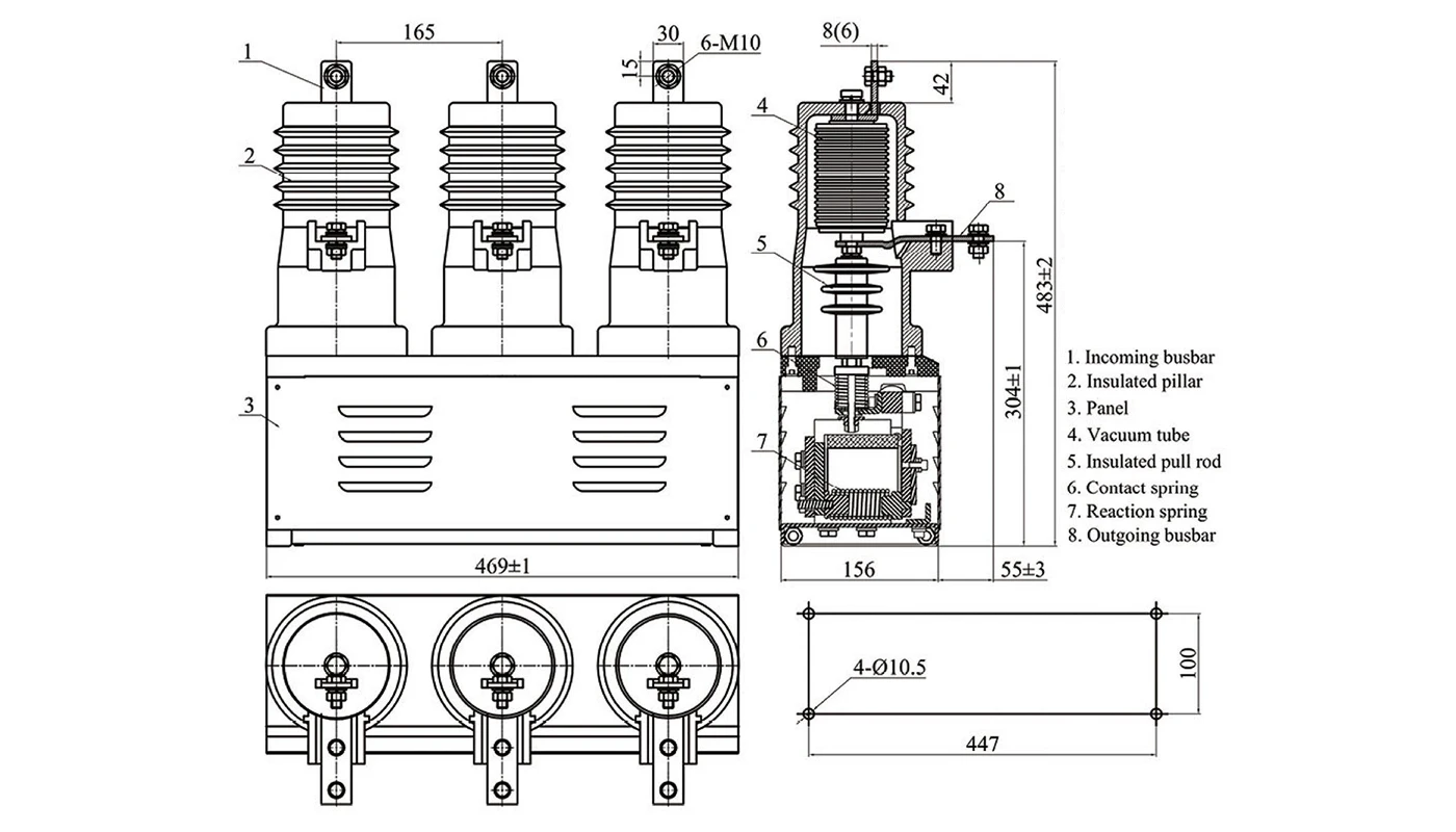
Outline & mounting dimensions — CKG4-□/12FD / 12FC / 12F□B□□
Representative outline and mounting dimensions for the standard, permanent magnet and back-to-back capacitor types. Use these drawings for panel layout and busbar design, and confirm key dimensions against the latest XBRELE engineering data.
This group of CKG4 12 kV contactors covers special versions such as zero-bounce TL type, phase controlled 12X□□ and enclosed 12XF□ types, as well as the 12-2 two-pole configuration. All models are designed for AC 50 Hz systems with rated voltage 12 kV and rated current up to 630 A.
CKG4-□/12TL focuses on reducing contact bounce and improving reliability. CKG4-□/12X□□ and CKG4-□/12XF□ use phase controlled operating mechanisms to achieve flexible on-demand switching. CKG4-□/12-2 is an extreme two-pole design for two-phase applications where compact layout and high breaking capacity are required.
The combined table below compares the main technical parameters of CKG4-□/12TL, CKG4-□/12X□□, CKG4-□/12XF□ and CKG4-□/12-2, helping engineers select the correct special type for each project.
Main technical parameters — CKG4-□/12TL / 12X□□ / 12XF□ / 12-2
Comparative ratings for zero-bounce, phase controlled, enclosed phase controlled and two-pole types. Values are taken from the original XBRELE datasheets and should be checked again during final design.
| No. | Item | Unit | CKG4-□/12TL | CKG4-□/12X□□ | CKG4-□/12XF□ | CKG4-□/12-2 |
|---|---|---|---|---|---|---|
| 1 | Rated voltage | kV | 12 | 12 | 12 | 12 |
| 2 | Rated current | A | 160 / 250 / 400 / 630 | 160 / 250 / 400 / 630 | 160 / 250 / 400 / 630 | 160 / 250 / 400 / 630 |
| 3 | Power-frequency withstand voltage (1 min) | kV | 42 | 42 | 42 | 42 |
| 4 | Lightning impulse withstand voltage | kV | 75 | 75 | 75 | 75 |
| 5 | Rated breaking current (AC-3 duty) | A | 8Ie, 25 operations | 8Ie, 25 operations | 8Ie, 25 operations | 8Ie, 25 operations |
| 6 | Rated making current (AC-3 duty) | A | 10Ie, 100 operations | 10Ie, 100 operations | 10Ie, 100 operations | 10Ie, 100 operations |
| 7 | Rated short-time withstand current | kA | 10Ie, 1.6 / 2.5 / 4 / 6.3 | 10Ie, 1.6 / 2.5 / 4 / 6.3 | 10Ie, 1.6 / 2.5 / 4 / 6.3 | 10Ie, 1.6 / 2.5 / 4 / 6.3 |
| 8 | Rated peak withstand current | kA | 25Ie, 4 / 6.3 / 10 / 16 | 25Ie, 4 / 6.3 / 10 / 16 | 25Ie, 4 / 6.3 / 10 / 16 | 25Ie, 4 / 6.3 / 10 / 16 |
| 9 | Overload withstand current | kA | 15Ie, 2.4 / 3.8 / 6 / 9.45 | 15Ie, 2.4 / 3.8 / 6 / 9.45 | 15Ie, 2.4 / 3.8 / 6 / 9.45 | 15Ie, 2.4 / 3.8 / 6 / 9.45 |
| 10 | Rated operating sequence | — | 0–180s–CO–180s–CO | 0–180s–CO–180s–CO | 0–180s–CO–180s–CO | 0–180s–CO–180s–CO |
| 11 | Rated contact gap | mm | 5.5 ± 0.5 | 5.5 ± 0.5 | 5.5 ± 0.5 | 5.5 ± 0.5 |
| 12 | Overtravel | mm | ≥ 1.5 | ≥ 1.5 | ≥ 1.5 | ≥ 1.5 |
| 13 | Simultaneity of poles | ms | ≤ 2 | ≤ 3 (Phase control) | ≤ 3 (Phase control) | ≤ 2 |
| 14 | Mechanical life | Operations (×104) | 50 | 50 | 50 | 50 |
| 15 | Electrical life (AC-3 duty) | Operations (×104) | 25 | 25 | 25 | 25 |
| 16 | Electrical life (AC-4 duty) | Operations (×104) | 10 | 10 | 10 | 10 |
Outline & mounting dimensions — CKG4-□/12TL / 12X□□ / 12XF□ / 12-2
Representative outline and mounting dimensions for the zero-bounce, phase controlled, enclosed and two-pole types. Use these drawings when designing switchgear panels and busbar arrangements.
The CKG4-□/12M series is designed for mechanical interlocking between two or more 12 kV vacuum contactors. Typical applications include forward/reverse conversion of high-voltage motors, dual-feeder interlocking and safety interlocking between different circuits in metal-clad switchgear.
After adding the mechanical interlock device, the two contactors cannot be closed at the same time, which greatly improves operation safety. The series keeps the same main electrical performance as the standard CKG4 12 kV vacuum contactors, with high reliability, long electrical and mechanical life and low maintenance requirements.
The combined table below compares the key ratings of CKG4-□/12M-5, CKG4-□/12M-4 and CKG4-□/12M-3 so that engineers can quickly select the appropriate interlocking configuration for each project.
Main technical parameters — CKG4-□/12M-5 / CKG4-□/12M-4 / CKG4-□/12M-3
Mechanical interlocking type vacuum contactors, sharing the same electrical ratings. Values are referenced from the XBRELE catalogue and should be checked against the latest datasheets for critical design work.
| No. | Item | Unit | CKG4-□/12M-5 | CKG4-□/12M-4 | CKG4-□/12M-3 |
|---|---|---|---|---|---|
| 1 | Rated voltage | kV | 12 | 12 | 12 |
| 2 | Rated current | A | 160 / 250 / 400 / 630 | 160 / 250 / 400 / 630 | 160 / 250 / 400 / 630 |
| 3 | Power-frequency withstand voltage (1 min) | kV | 42 | 42 | 42 |
| 4 | Lightning impulse withstand voltage | kV | 75 | 75 | 75 |
| 5 | Rated breaking current (AC-3 duty) | A | 8Ie, 25 operations | 8Ie, 25 operations | 8Ie, 25 operations |
| 6 | Rated making current (AC-3 duty) | A | 10Ie, 100 operations | 10Ie, 100 operations | 10Ie, 100 operations |
| 7 | Rated short-time withstand current | kA | 10Ie, 1.6 / 2.5 / 4 / 6.3 | 10Ie, 1.6 / 2.5 / 4 / 6.3 | 10Ie, 1.6 / 2.5 / 4 / 6.3 |
| 8 | Rated peak withstand current | kA | 25Ie, 4 / 6.3 / 10 / 16 | 25Ie, 4 / 6.3 / 10 / 16 | 25Ie, 4 / 6.3 / 10 / 16 |
| 9 | Overload withstand current | kA | 15Ie, 2.4 / 3.8 / 6 / 9.45 | 15Ie, 2.4 / 3.8 / 6 / 9.45 | 15Ie, 2.4 / 3.8 / 6 / 9.45 |
| 10 | Rated operating sequence | — | 0–180s–CO–180s–CO | 0–180s–CO–180s–CO | 0–180s–CO–180s–CO |
| 11 | Rated contact gap | mm | 5.5 ± 0.5 | 5.5 ± 0.5 | 5.5 ± 0.5 |
| 12 | Overtravel | mm | ≥ 1.5 | ≥ 1.5 | ≥ 1.5 |
| 13 | Simultaneity of poles | ms | ≤ 2 | ≤ 2 | ≤ 2 |
| 14 | Mechanical life | Operations (×104) | 50 | 50 | 50 |
| 15 | Electrical life (AC-3 duty) | Operations (×104) | 25 | 25 | 25 |
| 16 | Electrical life (AC-4 duty) | Operations (×104) | 10 | 10 | 10 |
Outline & mounting dimensions — CKG4-□/12M-5 / 12M-4 / 12M-3
Representative outline and mounting dimensions for three mechanical interlocking arrangements. Use these drawings for panel layout, interlock mechanism mounting and busbar design, and confirm key dimensions with the latest XBRELE engineering data.
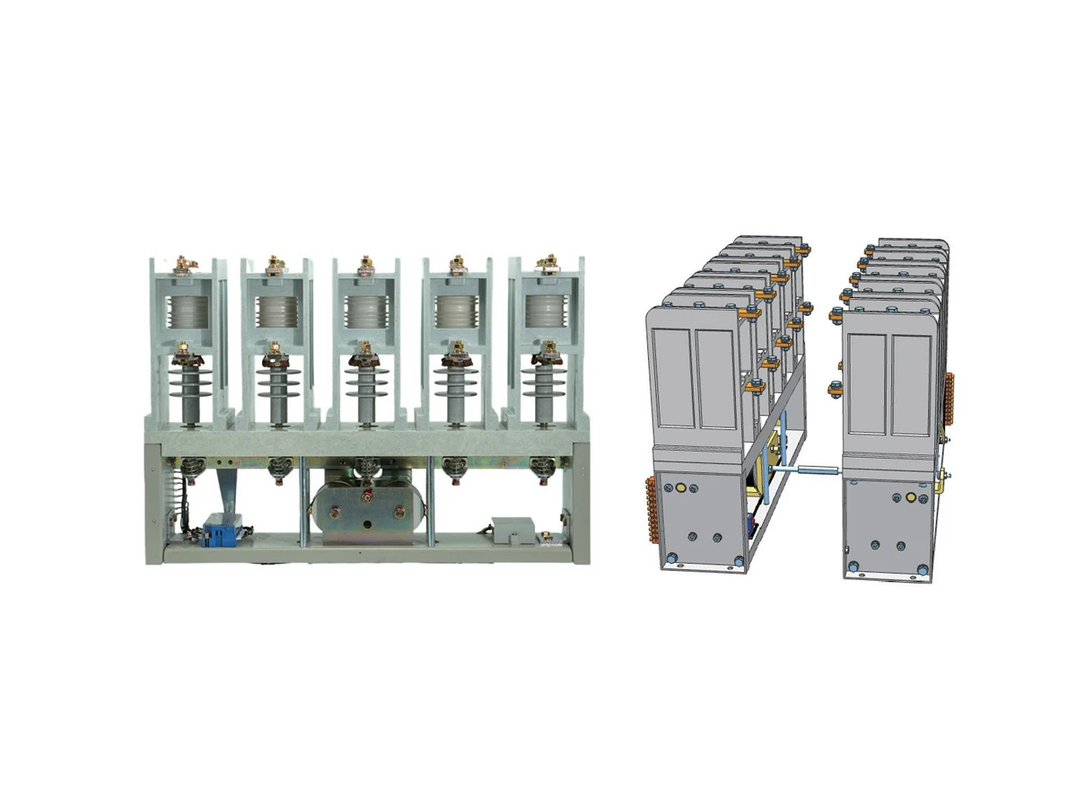
The high-current CKG4 family (800 A to 1250 A) is designed for heavy-duty feeders, large motors and capacitor bank circuits in 12 kV metal-clad switchgear. These models provide enhanced thermal performance, stronger making/breaking capacity and long-life contact systems.
Both CKG4-800/12 and CKG4-1000–1250/12 share the same key electrical ratings, while the physical structure and heat-dissipation design differ to support higher continuous and short-time currents.
Main technical parameters — CKG4-800/12 & CKG4-1000–1250/12
Unified high-current ratings for both 800 A and 1000–1250 A versions. Confirm against latest XBRELE datasheets for final design.
| No. | Item | Unit | CKG4-800/12 | CKG4-1000–1250/12 |
|---|---|---|---|---|
| 1 | Rated voltage | kV | 12 | 12 |
| 2 | Rated current | A | 800 | 1000 / 1250 |
| 3 | Power-frequency withstand voltage (1 min) | kV | 42 | 42 |
| 4 | Lightning impulse withstand voltage | kV | 75 | 75 |
| 5 | Rated breaking current (AC-3 duty) | A | 8Ie | 8Ie |
| 6 | Rated making current (AC-3 duty) | A | 10Ie | 10Ie |
| 7 | Rated short-time withstand current | kA | 25 | 31.5 |
| 8 | Rated peak withstand current | kA | 63 | 80 |
| 9 | Main circuit resistance | µΩ | ≤ 60 | ≤ 50 |
| 10 | Mechanical life | Operations (×104) | 50 | 50 |
| 11 | Electrical life (AC-3 duty) | Operations (×104) | 25 | 25 |
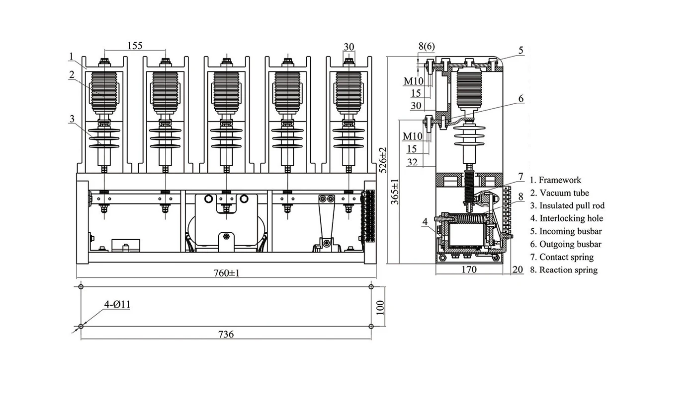
Outline & mounting dimensions — CKG4-800/12 & CKG4-1000–1250/12
Representative outline drawings for both high-current structures. Use for panel layout, busbar design and thermal planning.
CKG vacuum contactors can be configured with different control coils, auxiliary contacts, interlocks and high-current or capacitor-duty versions, so panel builders can match the exact requirements of their medium voltage switchgear projects.
CKG3-7.2 and CKG4-12 contactors support a wide range of control voltages and duty classes, allowing you to standardize control schemes across different panels.
Flexible auxiliary and interlocking options help implement safe interlocks and status signalling in MV switchgear and motor control centers.
Beyond standard ratings, CKG4 contactors offer high-current and special-purpose versions for demanding feeders, motors and capacitor banks.
Behind every CKG vacuum contactor there is a controlled manufacturing flow – from vacuum interrupter and magnetic system assembly to routine testing – designed to ensure long-term reliability in medium voltage switchgear panels.
XBRELE manufactures the vacuum interrupter assemblies, magnetic circuits, operating mechanisms and main circuits in a coordinated process. Each step is monitored and recorded for traceability of every CKG3-7.2 and CKG4-12 vacuum contactor.
Vacuum interrupters are checked for contact stroke, over-travel and resistance, then built into insulated supports together with fixed and moving contacts for the main circuit.
Closing and opening coils, yokes and armatures are assembled and adjusted so that magnetic forces, pick-up voltage and drop-out characteristics meet CKG design requirements.
The operating mechanism is assembled, lubricated and tuned so that opening and closing speeds, bounce time and synchronism satisfy the specified limits for frequent switching duty.
Main terminals, auxiliary contacts, mechanical interlocks and mounting parts are configured according to the required CKG contactor scheme for OEM panels or retrofit projects.
Each assembled contactor passes electrical, dielectric and mechanical tests before packing, with results linked to the serial number for future traceability.
Electrical routine tests verify insulation level and switching performance under specified operating conditions.
Routine-test records can be supplied with the shipment if required.
FAT / QAP / ITP witness testing can be arranged for utility, industrial or EPC projects.
XBRELE supports OEM panel builders, industrial users and distributors with predictable delivery, export-ready packing and engineering documentation for CKG3-7.2 and CKG4-12 medium voltage vacuum contactors.
Typical delivery times for CKG vacuum contactors, depending on configuration and quantity.
CKG vacuum contactors are packed for long-distance sea or land transportation with proper protection for mechanisms and terminals.
XBRELE provides the documentation and technical support needed for MV panel design and project approval involving CKG contactors.
Below are typical questions from OEM panel builders, industrial users and distributors when selecting XBRELE CKG3-7.2 and CKG4-12 medium voltage vacuum contactors for motor, feeder and capacitor switching.