Need Full Specifications?
Download our 2025 Product Catalog for detailed drawings and technical parameters of all switchgear components.
Get CatalogDownload our 2025 Product Catalog for detailed drawings and technical parameters of all switchgear components.
Get CatalogDownload our 2025 Product Catalog for detailed drawings and technical parameters of all switchgear components.
Get Catalog
An earthing switch is a mechanical switching device that connects de-energized circuit conductors directly to earth potential, eliminating induced voltages, trapped capacitive charges, and residual energy that could injure maintenance personnel. Unlike circuit breakers or load-break switches, earthing switches carry no interrupting capability—their sole function is bonding isolated conductors to ground before workers access exposed equipment.
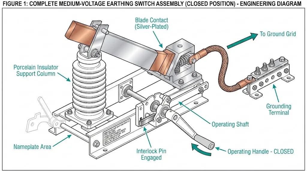
In medium-voltage systems rated 3.6 kV to 40.5 kV, earthing switches mount on busbars, cable terminations, and feeder compartments within metal-enclosed switchgear. The device appears mechanically simple: a conductive blade pivoting into a fixed contact connected to the station grounding grid. Yet this simplicity masks critical engineering requirements governing making capacity, operating sequence, and interlocking logic.
The earthing switch represents the final safety barrier before human hands touch exposed conductors. After upstream circuit breakers open and disconnectors create visible isolation gaps, the earthing switch provides positive grounding—a deliberate short-circuit to earth that guarantees zero voltage regardless of induction from parallel circuits, backfeed through transformer windings, or capacitive coupling from adjacent phases.
Without proper earthing, technicians working on “isolated” equipment face lethal shock hazards from sources invisible to standard voltage indicators. Induced voltages from parallel transmission lines routinely exceed 1,000 V on ungrounded conductors. Trapped charges on cable capacitance can deliver fatal current even hours after isolation.
The earthing switch eliminates these hazards by providing a low-impedance path to ground. Contact resistance values typically remain below 200 μΩ, ensuring effective fault current conduction. The grounding path from main contacts through the operating mechanism to the earthed frame must carry prospective fault current without excessive temperature rise—usually limited to 250°C at contact surfaces during short-time duty.
Making capacity—the maximum prospective current an earthing switch can safely close onto—represents the most critical performance parameter distinguishing protective devices from standard grounding equipment.
Under normal conditions, an earthing switch closes onto a fully isolated, voltage-free conductor. The operation is uneventful. But what happens when a technician closes the earthing switch while the circuit remains energized due to procedural error, failed isolation, or incorrect switching sequence?
The earthing switch must survive this fault scenario without welding shut, fragmenting, or producing an uncontrolled arc. This survival capability defines making capacity.
IEC 62271-102 classifies earthing switches by making capacity requirements:
Class E0: No rated making capacity. Designed exclusively for grounding de-energized circuits where accidental energization risk is negligible.
Class E1: Induced current making capacity up to 160 A. Handles capacitive and inductive coupling from parallel energized circuits.
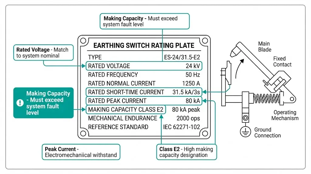
Class E2: High making capacity reaching 25 kA to 63 kA for 1-second duration. Protects against scenarios where circuits are mistakenly believed to be de-energized.
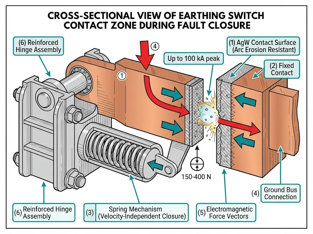
The making capacity formula considers peak current Ipeak = k × Irms, where k typically equals 2.5 for 50 Hz systems and 2.6 for 60 Hz systems, accounting for DC offset in asymmetrical fault currents. For a Class E2 switch rated at 40 kArms, the peak making current reaches approximately 100 kA.
Contact mechanisms in Class E2 earthing switches must withstand severe electromagnetic forces during fault closure. Key design elements include:
[Expert Insight: Making Capacity Field Observations]
- In assessments across 40+ substation installations, Class E2 switches have successfully contained fault closures without contact welding when properly rated to system fault levels
- Legacy installations often contain E0-class switches inadequate for modern protection requirements—upgrade during scheduled outages
- Post-fault inspection is mandatory: even successful fault closures cause measurable contact erosion
- Contact resistance trending above 300 μΩ after fault duty indicates replacement requirement
Earthing switch operation follows rigid sequencing rules. Deviation creates life-threatening conditions.
The earthing switch closes last—only after upstream isolation is confirmed.
The earthing switch opens first—before any isolation gap closes.
Closing the earthing switch before opening the circuit breaker creates a bolted three-phase fault through the grounding system. If the breaker remains closed, fault current flows until protective relays trip upstream devices—potentially causing arc flash incidents, equipment destruction, and fatalities.
Opening the disconnector while load current flows produces a sustained arc. Disconnectors lack arc-extinguishing capability. The arc may persist for seconds, vaporizing contacts and creating explosive plasma conditions.
Both errors have caused documented fatalities. Sequence enforcement through interlocking systems is non-negotiable.

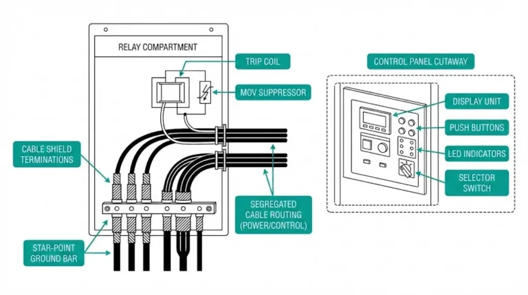
Mechanical interlocks use physical blocking pins, cams, or lever arrangements that prevent one device from operating unless another device sits in the correct position. They require no power supply—functioning during complete station blackout exactly when procedural errors become most likely.
| Device State | Interlock Effect |
|---|---|
| Circuit breaker closed | Earthing switch blocked from closing |
| Earthing switch closed | Disconnector blocked from closing |
| Disconnector closed | Earthing switch blocked from closing |
These hardware barriers convert procedural rules into physical constraints. A technician cannot close the earthing switch while the circuit breaker remains engaged—the mechanism physically prevents blade movement regardless of intent or urgency.
In modern vacuum circuit breaker panels, manufacturers integrate mechanical interlocks directly into the switchgear framework. The VCB withdrawable unit must reach the test or isolated position before the earthing switch operating handle unlocks.

[Expert Insight: Interlock System Realities]
- Interlock defeat remains the leading cause of switching-related fatalities—any bypassed interlock demands immediate investigation and retraining
- Mechanical interlocks require periodic lubrication; seized mechanisms create false security
- Auxiliary position contacts must align with actual blade position—verify during routine maintenance
- Key interlock systems (Castell, Kirk) provide cross-device enforcement ideal for outdoor switchyards with distributed equipment
Electrical interlocks use auxiliary contacts, position sensors, and control logic to inhibit closing commands. They enable remote operation and motor-driven sequences while maintaining safety verification.
A typical scheme routes the circuit breaker’s 52b auxiliary contact in series with the earthing switch close circuit. When the breaker is closed (52b contact open), the earthing switch close command cannot complete electrically.
Key interlock systems employ trapped-key principles. A key locked in one device must be released before another device can operate:
| Feature | Mechanical | Electrical | Key-Based |
|---|---|---|---|
| Power required | No | Yes | No |
| Remote operation capable | No | Yes | No |
| Cross-device enforcement | Limited | Yes | Yes |
| Blackout functionality | Full | None | Full |
| Tamper resistance | Moderate | Low | High |
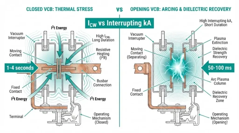
Understanding vacuum circuit breaker working principles clarifies why interlocks coordinate breaker position with earthing switch permission—the VCB must complete arc extinction before grounding becomes safe.
Before specifying an earthing switch, confirm these parameters match system requirements:
| Parameter | Typical MV Range | Specification Notes |
|---|---|---|
| Rated voltage | 3.6 kV to 40.5 kV | Match system nominal voltage |
| Rated short-time withstand current | 16 kA to 40 kA (1s or 3s) | Thermal withstand capability |
| Rated peak withstand current | 40 kA to 100 kA | Electromechanical force resistance |
| Rated short-circuit making current | 40 kA to 100 kA peak | Must equal or exceed system fault level |
| Rated normal current | 630 A to 3150 A | Continuous thermal rating |
The short-circuit making current must equal or exceed the maximum prospective fault current at the installation point. For a 31.5 kA symmetrical fault-level system, specify at least 80 kA peak making capacity. Detailed vacuum circuit breaker ratings guidance helps coordinate earthing switch selection with upstream protection devices.
Interlock defeat: Technicians sometimes bypass interlocks for urgent work. This practice has directly caused fatalities. Any defeated interlock triggers immediate investigation.
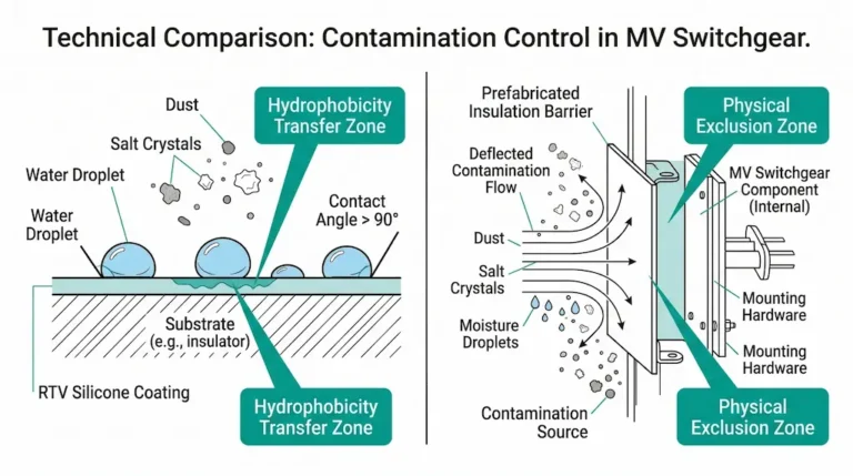
Coastal corrosion: Salt fog degrades unpainted steel components within months. Specify stainless steel or hot-dip galvanized construction for marine environments.
Insufficient legacy ratings: Older installations often contain earthing switches rated only for de-energized closing. These devices fail catastrophically when closed onto live circuits.
Auxiliary contact drift: Position feedback contacts lose adjustment after repeated operations. Misalignment creates dangerous false indications in control systems.
Quality switchgear components including properly rated earthing switches form the foundation of reliable medium-voltage installations.
Q: What is the difference between an earthing switch and a grounding switch?
A: They describe the same device—“earthing switch” follows IEC terminology while “grounding switch” reflects North American usage; both connect de-energized conductors to earth potential.
Q: Can an earthing switch interrupt load current?
A: No. Earthing switches lack arc-extinguishing capability and must close only onto de-energized, isolated circuits under normal operating conditions.
Q: What happens if an earthing switch closes onto a live circuit?
A: A bolted short-circuit fault occurs; Class E2 earthing switches with adequate making capacity survive without contact welding, while undersized devices may weld shut or fragment.
Q: How often should earthing switch contacts be inspected?
A: Annual inspection during routine maintenance is typical, with immediate examination required after any fault-closure event or when contact resistance exceeds 250 μΩ.
Q: Why are mechanical interlocks preferred over electrical interlocks alone?
A: Mechanical interlocks function without power supply, maintaining safety enforcement during station blackouts when procedural errors become statistically more likely.
Q: What making capacity should I specify for a 31.5 kA fault-level system?
A: Specify minimum 80 kA peak making capacity, calculated using the DC offset factor of approximately 2.5 times the symmetrical RMS fault current value.
Q: How do key interlock systems differ from mechanical interlocks?
A: Key interlocks use transferable trapped keys to enforce sequences across physically separated devices, while mechanical interlocks provide direct physical blocking between adjacent equipment only.
External Reference: IEC 62271-102 defines comprehensive requirements for high-voltage disconnectors and earthing switches, including making capacity test procedures and classification criteria. Access the current edition via IEC Webstore.