Need Full Specifications?
Download our 2025 Product Catalog for detailed drawings and technical parameters of all switchgear components.
Get CatalogDownload our 2025 Product Catalog for detailed drawings and technical parameters of all switchgear components.
Get CatalogDownload our 2025 Product Catalog for detailed drawings and technical parameters of all switchgear components.
Get Catalog
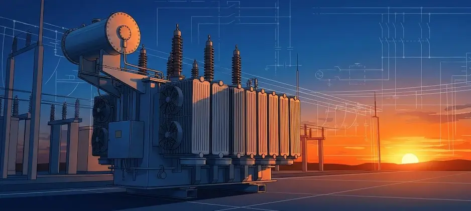
If you look up at a utility pole or peer behind the fence of an electrical substation, you will see them: silent, blocky sentinels humming quietly. These are electric transformers, and without them, modern civilization as we know it would grind to a halt.
While we often take electricity for granted, the journey of power from a turbine to your toaster involves a complex balancing act of voltage and current. The transformer is the device that makes this journey possible. It is the reason we can transmit power efficiently across continents yet safely charge a smartphone at our bedside.
As we move into 2025, the role of the transformer is evolving. With the rise of renewable energy sources like wind and solar, these devices are no longer just passive bridges; they are becoming the intelligent nodes of the smart grid.
This guide moves beyond simple definitions. We will explore the physics, the engineering challenges, the critical differences between equipment types, and the operational nuances that every student, technician, and industry professional should understand.
At its most fundamental level, a transformer is a static electrical machine. Unlike motors or generators, it has no moving parts (which contributes to its exceptionally high efficiency and long lifespan).
A transformer transfers electrical energy between two or more circuits through electromagnetic induction. Crucially, it does this without changing the frequency.
Its primary job is to “transform” voltage levels:
Because transformers rely on magnetic fields rather than rotating shafts or brushes, they suffer minimal mechanical wear. This allows them to operate continuously for decades—often 30 to 40 years—with relatively low maintenance compared to dynamic machinery like turbines or diesel generators.
To understand the “why,” we must look at the physics of power loss.
When electricity travels through a wire, the wire resists the flow, creating heat. This wasted energy is calculated as I²R (Current squared times Resistance). The key takeaway here is the squared factor. If you double the current, you quadruple the energy loss.
Power plants are often located hundreds of miles from cities. Sending electricity at standard household voltages (e.g., 230V or 110V) over that distance is impossible. To deliver usable power, the current required would be massive, the copper cables would need to be impossibly thick (feet in diameter), and most energy would be lost as heat before reaching the destination.
Transformers solve this by manipulating the relationship between Voltage (V) and Current (I). Since Power (P) = V × I:
Without this ability to toggle between high-voltage/low-current and low-voltage/high-current, national power grids would be economically and physically impossible.
The operation of a transformer relies on a phenomenon discovered in the 1830s: Faraday’s Law of Electromagnetic Induction.
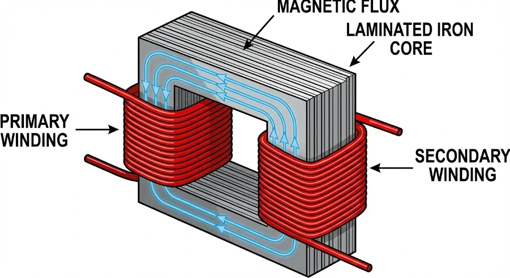
Imagine two separate coils of wire that are not touching but are wrapped around the same metal loop.
It is also important to mention Lenz’s Law, which dictates the direction of the induced voltage. It states that the induced electromotive force (EMF) always opposes the change in magnetic flux that produced it. This principle is critical for understanding the “back pressure” (Back EMF) that transformers exert on the power source, which helps regulate the current draw.
Why not DC? Direct Current (DC) flows in one direction at a constant rate. It would create a static, unchanging magnetic field. Without a changing field, no voltage is induced in the secondary coil. This is why transformers only work with AC, and why Edison’s DC grid eventually lost to Tesla’s AC system.
The amount of voltage change is directly proportional to the number of wire turns in the coils. This is defined by a simple yet powerful formula:
Vp / Vs = Np / Ns
If the secondary coil has twice as many turns as the primary, the output voltage will be double the input voltage. This ratio allows engineers to design transformers with precise output targets.
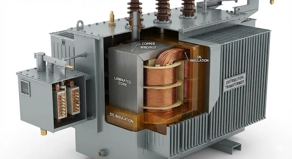
A transformer might look like a simple metal box, but inside, it is a marvel of materials science and thermal engineering.
A transformer might look like a simple metal box, but inside, it is a marvel of materials science and thermal engineering.
The core acts as the path of least resistance for magnetic flux. It isn’t a solid block of steel.
These are the coils that carry the current.
Heat is the enemy of electrical equipment. Proper selection depends on the installation environment:
For a deep dive into choosing the right system for your project, read our comparison on Dry Type vs Oil Filled Transformers.
Visible on top of many oil transformers, the Conservator Tank is a cylindrical expansion vessel. As the oil heats up and expands, it flows into this tank. Connected to it is the Breather, often filled with purple or blue Silica Gel. This device removes moisture from the air before it enters the tank, ensuring the insulating oil remains dry and effective.
These are the ceramic or composite “horns” on top of the transformer. They allow the high-voltage energized conductors to pass through the grounded metal tank without arcing over.
Transformers are categorized based on their function and construction.
While they look similar, their engineering philosophy differs significantly.
| Feature | Power Transformer | Distribution Transformer |
|---|---|---|
| Operating Load | Always operates near full load (100%). | Load fluctuates wildly (high in evening, low at night). |
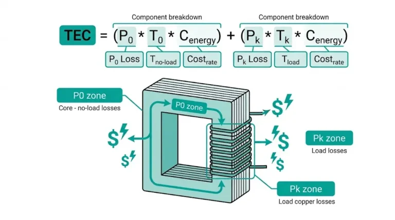
| Efficiency Design | Optimized for full-load copper losses. | Optimized for core losses (iron losses) to ensure “All-Day Efficiency.” |
| Voltage Ratings | High (33kV, 66kV, 400kV+). | Lower (11kV down to 400V/230V). |
| Network Position | Transmission receiving/sending ends. | The “last mile” delivery to customers. |
For deep dives into specification differences, referring to specialized resources on Power Distribution Transformers is highly recommended for procurement officers and engineers.
Transformers are among the most efficient machines on earth, often achieving 98% to 99.5% efficiency. However, the remaining loss manifests as heat and noise.
That buzzing sound you hear near a transformer isn’t electricity escaping. It is Magnetostriction. The magnetic field causes the steel core laminations to physically expand and contract slightly 100 or 120 times a second (depending on 50Hz or 60Hz frequency). This physical vibration creates the audible hum.
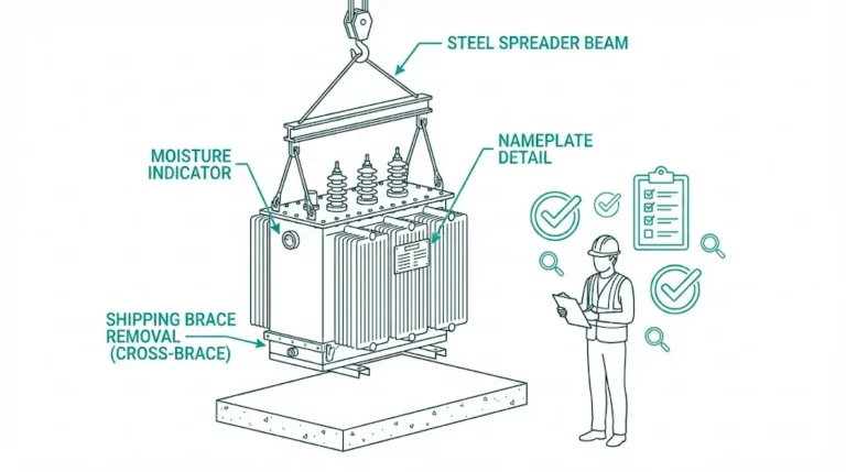
A transformer failure can be catastrophic, leading to fires or massive blackouts. Therefore, protection is paramount. Engineers should follow a rigorous transformer testing checklist during commissioning.
In oil-filled transformers, this clever device detects gas bubbles. If an internal short circuit occurs, the oil decomposes into gas. The relay catches this gas and trips the circuit breaker before the transformer explodes.
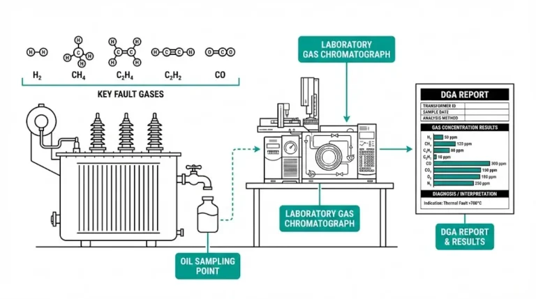
Think of this as a blood test for transformers. Engineers take oil samples and analyze dissolved gases. High levels of acetylene, for example, indicate internal arcing; high levels of carbon monoxide indicate paper insulation is burning. This allows for predictive maintenance.
In modern maintenance, engineers use thermal cameras to scan the transformer tank and bushings. Hot spots usually indicate loose connections, blocked cooling fins, or internal winding faults that are invisible to the naked eye.
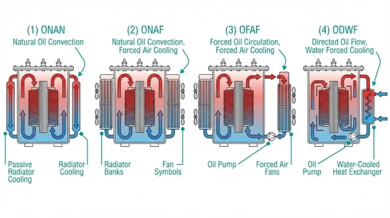
You might see codes like ONAN or ONAF on a nameplate. These standards are often defined by the IEC (International Electrotechnical Commission) to ensure global consistency:
Q: Can a transformer convert AC to DC? A: No. A transformer only changes voltage levels of AC power. To convert AC to DC, you need a rectifier. To convert DC to AC, you need an inverter.
Q: Why do transformers explode? A: Explosions are rare but usually occur due to insulation failure leading to a short circuit. This creates a massive arc, instantly vaporizing the cooling oil into rapidly expanding gas. If the pressure relief valve fails, the tank can rupture.
Q: What is the difference between a dry-type and liquid-filled transformer? A: Liquid-filled units use oil for cooling and are more efficient but pose a fire risk (outdoor use). Dry-type units use air/resin, are fire-resistant, but typically larger and more expensive for the same power rating (indoor use).
Q: Why is the transformer rating in kVA and not kW? A: Manufacturers rate transformers in kVA (Apparent Power) because they don’t know what kind of load (Power Factor) the user will connect. The heating losses depend on Current (Amps), not just the active power (Watts).
Q: What is the lifespan of a transformer? A: With proper maintenance (oil testing, cleaning bushings), a transformer can last 25 to 40 years. However, overloading and high temperatures can significantly degrade the insulation paper, shortening its life.
The electric transformer is more than just a box of copper and steel; it is the enabler of the modern electrical age. From the massive step-up units at nuclear power plants to the small green box on your front lawn, these devices maintain the delicate balance of voltage and current that keeps our world running.
Understanding how they work—the interplay of magnetism, induction, and thermal management—provides a deeper appreciation for the grid’s complexity. For engineers, getting the specifications right means the difference between a reliable network and costly downtime.specifications right means the difference between a reliable network and costly downtime.
Do not leave your power infrastructure to chance. Whether you are upgrading a facility or planning a new subdivision, selecting the right transformer class and sizing is critical.
Talk to an engineer today to analyze your load requirements and get expert guidance tailored to your power system needs.
A comprehensive masterclass for power professionals. This 2025 edition covers foundational physics of arc quenching, internal switchgear architecture, and the evolution of digital circuit protection for smart grids.
Download Educational Guide