Need Full Specifications?
Download our 2025 Product Catalog for detailed drawings and technical parameters of all switchgear components.
Get CatalogDownload our 2025 Product Catalog for detailed drawings and technical parameters of all switchgear components.
Get CatalogDownload our 2025 Product Catalog for detailed drawings and technical parameters of all switchgear components.
Get Catalog
Last updated: 2026-12-21
Reading time: ~10–12 minutes
Audience: maintenance technicians, panel builders, electrical students, procurement engineers
Scope: LV–MV “fundamentals + selection + installation + inspection + troubleshooting”
Safety note: Educational guide only. For real work, follow site safety rules, applicable electrical codes, and the manufacturer datasheet.
Understanding epoxy contact box basics helps you make safer and more reliable electrical connections—especially in distribution equipment, industrial systems, and MV switchgear assemblies. In simple terms, an epoxy contact box is an insulating enclosure designed to house and protect terminals/contacts, reducing risk from moisture, dust, accidental touch, and contamination-driven faults.
If you’re building or sourcing MV assemblies, epoxy insulation components are often part of a wider system of switchgear parts and interlocks—see XBRELE’s overview of High-Voltage Switchgear Components & Safety Interlocks.
This guide uses plain language first and explains technical terms as you go.
For a practical baseline of LOTO expectations (general industry), refer to OSHA’s standard: 29 CFR 1910.147 (Lockout/Tagout).
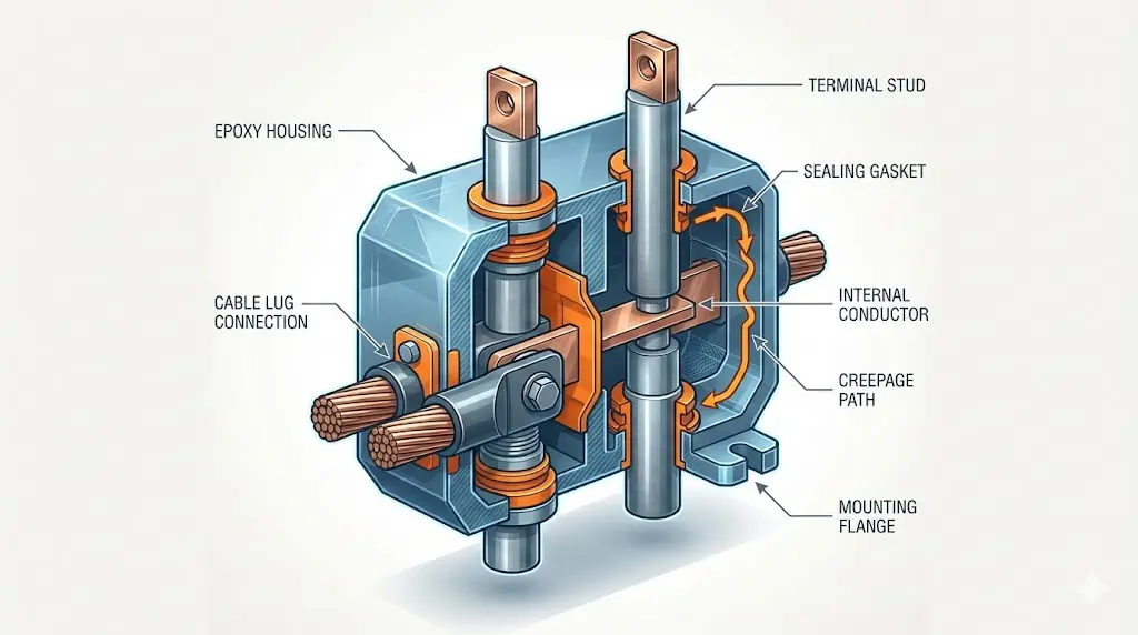
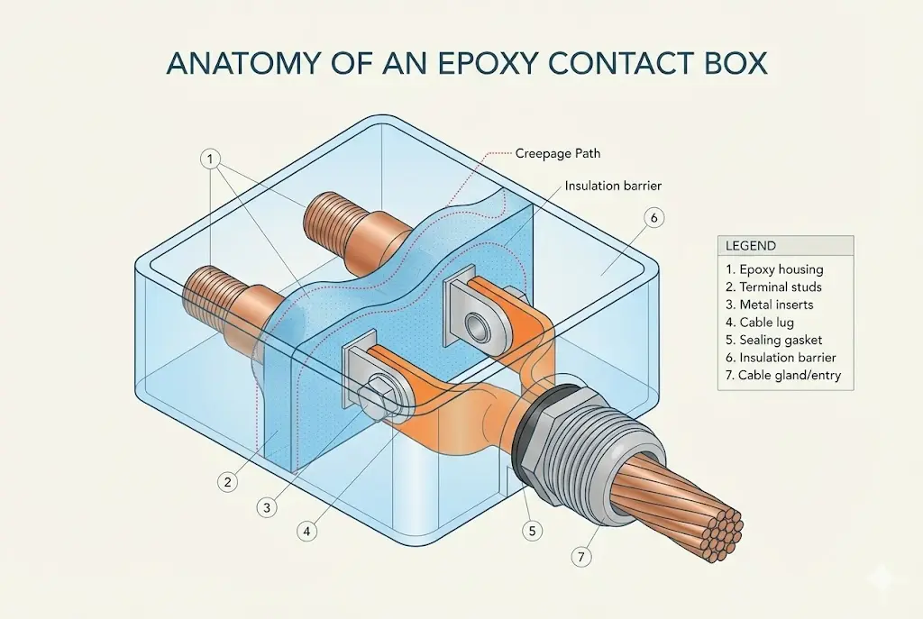
An epoxy contact box is a rigid enclosure made primarily from epoxy resin. Inside the enclosure are conductive components such as:
Epoxy may fully encapsulate conductors (cast-in) or form a sealed insulating housing around terminals—improving electrical isolation and environmental protection.
Epoxy resin is widely used because it can provide:
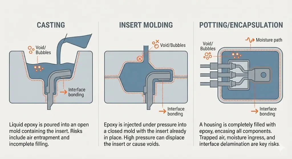
Not all epoxy contact boxes are “the same epoxy.” Performance is influenced by resin formulation and manufacturing process:
If you’re mapping epoxy contact boxes within an overall OEM insulation supply chain, you can also reference XBRELE’s manufacturing scope as a Switchgear Component Manufacturer.
The molded/cast outer body provides the primary insulation and mechanical structure. Good designs prioritize:
These conductive parts carry current. Reliability depends heavily on:
Most common field issue: loose terminal connections → higher resistance → overheating.
Updated for 2026: This article keeps the original technical framework and refreshes year-specific wording for current procurement, specification, and maintenance reference use.
Depending on the use case:
Epoxy acts as a dielectric barrier between live conductors and the outside environment. This reduces:
With appropriate sealing and design, epoxy contact boxes can help resist:
Common in panels and indoor switchboards:
Designed for exposure:
Some epoxy formulations include flame-retardant additives to meet project safety requirements.
Used in switchgear, distribution panels, and transformer connection areas to protect terminal interfaces.
Protects connection points exposed to vibration, dust, oil mist, and frequent maintenance.
Common in solar/wind systems to protect outdoor terminals and reduce weather-related degradation.
Epoxy housings can offer long service life due to rigidity and stable insulation geometry (when installed correctly).
By insulating live terminals and supporting reliable spacing, epoxy boxes help reduce shock and short-circuit risk.
You don’t need to memorize numbers—just confirm these items in the datasheet:
| Spec / Requirement | What to confirm | Why it matters |
|---|---|---|
| Voltage class | LV/MV suitability; insulation design intent | Wrong class risks tracking/breakdown |
| Creepage & clearance (MV) | Geometry is designed for your voltage environment | Prevents surface tracking/flashover |
| Current rating / conductor range | Terminal size matches conductor + lug | Avoids overheating and loose fit |
| Temperature range / heat rise | Ambient + load heating margin | Heat accelerates insulation aging |
| Sealing approach | gasket / gland / potting design | Determines moisture and dust resistance |
| IP requirement (if specified) | Rated level + proper installation steps | “Material” alone doesn’t give IP |
| Flame-retardant requirement | If project/spec demands it | Safety and compliance |
| Mounting method | panel/bracket, orientation limits | Avoids stress cracks and misfit |
| Serviceability | can you inspect/retorque terminals? | Reduces downtime and repeat failures |
If your project references IP codes, IEC has a concise explanation of IP ratings and what they do (and do not) guarantee: IEC IP ratings (IEC 60529).
Use this quick logic before choosing a model:

Inspection frequency (rule of thumb):
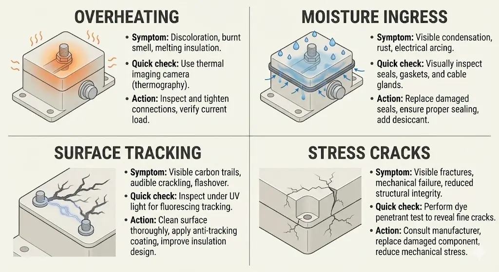
Symptoms: discoloration near terminal, smell, softened insulation, hot spots
Root cause: high contact resistance from poor torque, wrong lug, contamination, vibration
Action: de-energize → inspect lug fit → clean mating surfaces → torque per datasheet → confirm conductor sizing
Symptoms: branch-like marks, carbon tracking, occasional discharge noise (severe cases)
Root cause: contamination + moisture + insufficient creepage distance or poor surface condition
Action: clean/replace affected parts → improve sealing/contamination control → confirm suitability for MV environment
Symptoms: corrosion, condensation, moisture residue
Root cause: gasket aging, poor cable entry sealing, installation errors
Action: replace gasket/glands → correct cable entry → improve moisture management
Symptoms: micro-cracks around mounting holes or corners
Root cause: overtightening, uneven mounting surface, impact
Action: replace if insulation integrity is compromised → correct mounting flatness → torque discipline
| Symptom | Likely cause | Quick check | Corrective action |
|---|---|---|---|
| Terminal discoloration / hot smell | loose joint / wrong lug / undersized conductor | inspect lug seating; check tightness; signs of heating | de-energize, clean, re-terminate, torque to spec, verify conductor size |
| Intermittent faults in humid weather | moisture ingress / poor sealing | gasket condition, gland seating, water path | replace gasket/gland, improve entry sealing, consider higher grade |
| Tracking marks on surface | contamination + moisture + MV stress | inspect for carbon paths and deposits | clean/replace, improve sealing/cleanliness, verify creepage/clearance design |
| Hairline cracks near mounting | overtightening / uneven mounting | check mounting surface flatness and torque | replace if needed, correct mounting, use proper torque/washer strategy |
A site reported corrosion near terminal hardware after seasonal temperature swings. Inspection showed gasket compression was uneven and cable glands were not fully seated. After replacing gaskets/glands and re-installing with clean sealing surfaces, moisture signs reduced significantly.
Lesson: outdoor performance is often decided by cable entry + gasket installation quality.
In a high-vibration environment, a box showed discoloration near one terminal. The lug was slightly loose, increasing contact resistance. After correcting strain relief, re-terminating, and torquing to spec, temperature rise symptoms stopped.
Lesson: many “epoxy problems” are actually connection + vibration control problems.
Some designs are water-resistant, but performance depends on sealing design, cable entry, gasket condition, and installation quality. Always verify the datasheet/IP requirement for your application.
Yes—many models are used in MV equipment, but suitability depends on insulation design (creepage/clearance) and correct installation.
In harsh environments or higher electrical stress, epoxy often offers better rigidity and insulation stability. For light-duty indoor use, engineered plastics may also be appropriate if rated correctly.
Usually minimal, but periodic inspection is recommended—especially for loose connections, cracks, and seal aging.
Yes, but only if the model is designed for outdoor service and installed with correct sealing and cable entry practices.
Some are flame-retardant, but you must confirm the exact epoxy formulation and project compliance requirements.
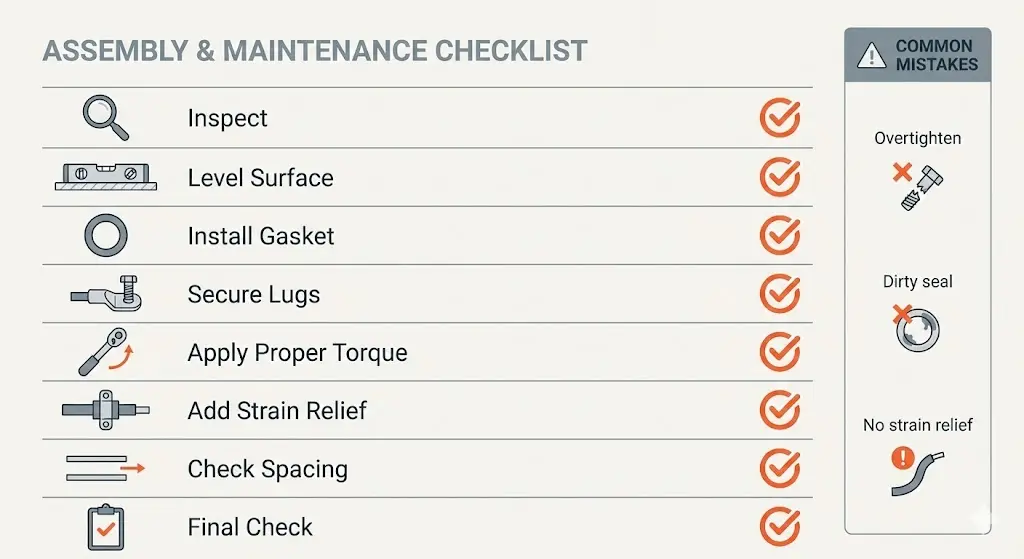
Epoxy contact boxes are widely used because they combine strong insulation, rigid protection, and long-term stability for critical terminal interfaces. Most failures can be avoided by choosing the right type for the environment and applying disciplined installation practices: flat mounting, correct torque, strain relief, and routine inspection.
If you’re building a complete insulation BOM for switchgear, you may also find it helpful to explore related epoxy insulation products like Indoor Epoxy Post Insulators & Capacitive Sensors, and download reference materials from the XBRELE Resources hub.
If you want a fast recommendation, send XBRELE the following:
👉 Contact XBRELE here: contact our engineering team