¿Necesita las especificaciones completas?
Descargue nuestro Catálogo de productos 2025 para obtener planos detallados y parámetros técnicos de todos los componentes de los equipos de conmutación.
Obtener catálogo
Descargue nuestro Catálogo de productos 2025 para obtener planos detallados y parámetros técnicos de todos los componentes de los equipos de conmutación.
Obtener catálogo Descargue nuestro Catálogo de productos 2025 para obtener planos detallados y parámetros técnicos de todos los componentes de los equipos de conmutación.
Obtener catálogo
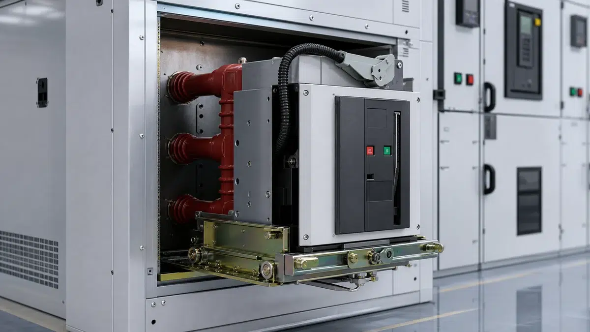
Selecting the correct closing coil for a vacuum circuit breaker (VCB) is one of those engineering decisions that looks straightforward on the surface but carries real consequences when done incorrectly. A mismatch between the coil's rated voltage and the substation's DC control power supply can result in a breaker that refuses to close under fault conditions, a coil that burns out during sustained energization, or—most dangerously—an intermittent failure that only appears during a high-stress switching event. The primary keyword driving this topic, **vcb closing coil sizing dc110v dc220v**, reflects a genuine and recurring challenge on medium-voltage switchgear projects: knowing exactly which coil to specify, why the voltage family matters, and how to verify your selection against the control system design.
This article covers the mechanical and electrical principles behind closing coil operation, the engineering differences between DC 110 V and DC 220 V control power schemes, the practical sizing criteria that govern coil selection, and the commissioning checks that confirm a correct installation.
—
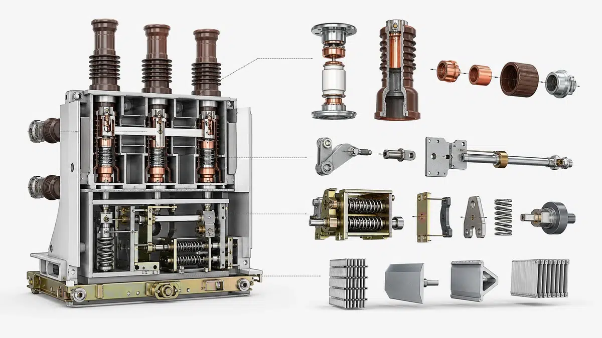
A vacuum circuit breaker in the medium-voltage class typically uses a stored-energy, spring-operated mechanism to achieve the high contact speed required for reliable interruption. Before a close command can be executed, the closing spring must be fully charged—either manually by a ratchet handle or automatically by an electric spring-charging motor. Once that spring is fully charged and the breaker is in the OPEN position, energizing the closing coil releases the spring latch.
According to Schneider Electric's EvoPact user guide, a spring-operated MV circuit breaker closes when its charged closing spring is released by the closing coil; the mechanism may be spring-charged manually or by the electrical charging motor. The closing coil itself does not supply the mechanical energy for contact travel—it only acts as the electromagnetic latch release. This distinction is critical for sizing because it means the coil's duty cycle is extremely short (typically 50–200 ms per operation), but the peak current drawn during that brief interval can be very high relative to a continuous-duty solenoid of similar physical size. The breaker rating selection guide helps translate the system duty into the breaker data that must be confirmed.
The practical implication for engineers: the closing coil is rated for an impulse duty, not a continuous or even intermittent thermal duty. If the auxiliary contact that de-energizes the coil after latch release fails to open promptly, the coil will overheat rapidly. This is why anti-pumping relays and the breaker's internal auxiliary switch sequencing are integral parts of the closing coil circuit, not optional accessories.
—
Many engineers approach coil selection by focusing on the coil's operating voltage and assume that any coil labeled "DC 110 V" will work interchangeably across all breaker types and all DC battery systems nominally running at 110 V. This assumption is incorrect, and the error is compounded when the installed battery system is actually floating at a different level under charge.
ABB's accessory documentation explicitly distinguishes nominal DC control-voltage families, including 110/127 V and 220/250 V ranges, and states that the applied coil must match the approved breaker and control-power design rather than be selected by nominal voltage alone. That guidance reflects the engineering reality that a closing coil is a voltage-specific electromagnetic device: its winding resistance, inductance, and core geometry are optimized for a defined voltage-current envelope. Substituting a 220 V coil onto a 110 V bus does not simply result in reduced force—it may not generate enough flux to release the latch at all. Conversely, applying a 110 V coil to a 220 V bus (even momentarily, due to bus transfer or inverter fault) can destroy the winding insulation within the first operating cycle.
The two dominant control voltage families in medium-voltage distribution substations are:
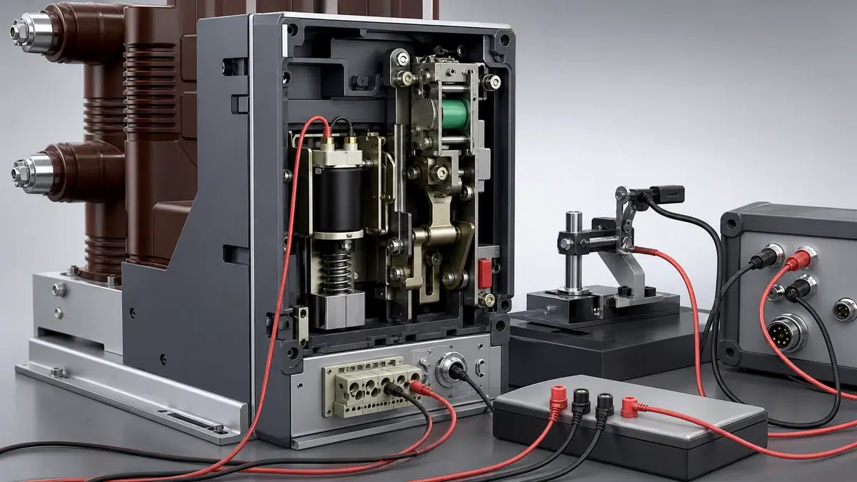
IEC 62271-1 is the common specification framework for high-voltage AC switchgear and controlgear above 1 kV; for a specific VCB control circuit, the project-controlled standard and manufacturer documentation remain the authority. This means the acceptable voltage band for closing coil operation—the minimum pickup voltage and the maximum sustained voltage—must be confirmed from the manufacturer's data sheet for the exact breaker model being installed, not from a generic IEC table alone. Review the XBRELE VCB portfolio as a practical starting point for matching the required breaker format to the application.
—
The DC 110 V control power scheme is historically common in utility distribution networks and industrial plant substations where the station battery is a 110 V nominal lead-acid or VRLA system. It offers several practical advantages:
**Lower Insulation Stress on Cabling and Terminal Blocks.** At 110 V DC, the control wiring can use lower-rated insulation, and the risk of arcing at terminal blocks during maintenance activities is reduced compared with 220 V systems. This is relevant in dense secondary wiring environments such as draw-out switchgear panels.
**Coil Resistance and Current.** A DC 110 V closing coil typically exhibits a nominal coil resistance in the range of 10–30 Ω (varies significantly by manufacturer and breaker frame size), resulting in initial inrush currents of several amperes. The coil current drops as the plunger seats and the flux path reluctance changes. Engineers sizing battery charger capacity and cable cross-sections must account for the transient current, not just the steady-state value.
**Battery Sizing Margin.** On a 110 V nominal system, the actual terminal voltage under float charge is often 115–125 V. Under end-of-discharge conditions the battery may fall to 88–100 V. The closing coil must be verified to operate reliably at the minimum end-of-discharge voltage, which is the critical case for close-on-fault events immediately following a protection trip—exactly when control power is most stressed. If a command or mechanism result is abnormal, continue with the VCB closing and opening troubleshooting guide.
**Typical Applications.** DC 110 V is frequently specified on 11 kV and 33 kV indoor switchgear in utilities, on industrial process plant switchrooms, and on distribution automation installations where the secondary equipment budget favors the lower-voltage control system.
—
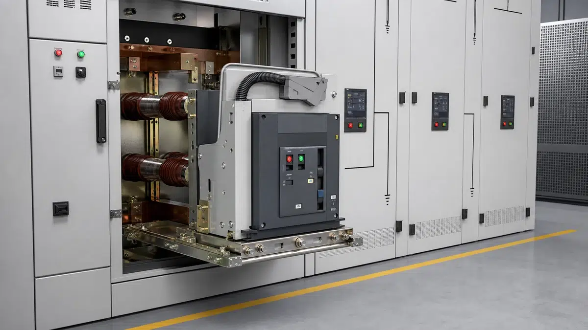
The DC 220 V control power scheme is common in transmission substations, large industrial facilities, and any application where the station battery system is already specified at 220 V nominal for the protection and SCADA loads. Sharing the same 220 V bus for both protection relaying and switchgear control reduces the number of battery systems and chargers needed on site.
**Higher Coil Resistance and Lower Current.** For the same coil force output, a 220 V coil winding requires approximately twice the resistance of a 110 V equivalent (from basic Ohm's law: double the voltage at the same power requires double the resistance). This means lower peak current draw per closing operation, which benefits cable sizing in long cable runs between the battery room and the switchgear panel. On large switchgear installations with many feeders, the cumulative current demand reduction on the 220 V DC bus is material.
**Winding Insulation.** The higher voltage demands more robust insulation between winding layers. This is accounted for in the manufacturing specification, but it reinforces the point that a 110 V coil must never be energized from a 220 V bus, even temporarily.
**Voltage Drop Sensitivity.** On a 220 V nominal system, the absolute voltage drop along the DC cable is smaller as a percentage of nominal compared with a 110 V system for a given cable resistance and current. This makes DC 220 V designs slightly more tolerant of long control cable runs before voltage drop becomes a sizing constraint.
**End-of-Discharge Performance.** Under the same discharge depth ratio, the 220 V battery will present a minimum terminal voltage around 176–198 V. Manufacturer data must be checked to confirm the coil reliably operates at this minimum, particularly for breakers with high spring preload forces.
—
Sizing a closing coil is not a freestanding calculation—it is a verification that the chosen coil is compatible with the available control power supply across its full tolerance envelope. The following process reflects sound engineering practice:
**Step 1: Confirm the nominal control voltage of the station DC system.** This comes from the project electrical design document, not the nameplate of the VCB itself. The breaker panel will be fed from a DC distribution board, and that board defines the nominal voltage family.
**Step 2: Obtain the manufacturer's approved closing coil part numbers for the specific breaker model and frame.** Because the closing coil must match the approved breaker design, the breaker manufacturer's accessory documentation is the authoritative source. Generic part numbers from distributor catalogs may not capture breaker-generation-specific differences.
**Step 3: Verify operating voltage range against battery performance.** Calculate the expected minimum DC bus voltage at the closing coil terminals under worst-case conditions: battery at end-of-discharge voltage, plus voltage drop in the cable run from the DC distribution board to the coil terminals. The result must exceed the coil's minimum pickup voltage from the manufacturer's data sheet.
**Step 4: Verify maximum voltage against coil damage threshold.** Calculate the maximum expected voltage at the coil: battery on float charge at maximum charger output, no voltage drop (cable resistance is additive at minimum voltage, not maximum). Confirm this does not exceed the coil's maximum permissible voltage.
**Step 5: Calculate DC cable sizing for the closing circuit.** The cable must carry the peak inrush current without excessive voltage drop. A common engineering rule is to limit the voltage drop in the closing coil circuit to no more than 10–15% of nominal voltage under peak current conditions, but the specific project specification or IEC 62271-1 as implemented in the project standard takes precedence.
**Step 6: Confirm anti-pumping and auxiliary contact sequencing.** The closing coil de-energization path must open the coil circuit within the time the manufacturer specifies to prevent coil overheating. Verify the auxiliary switch transition timing from the breaker mechanism datasheet.
—
One source of field problems arises from misunderstanding the relationship between the nominal DC voltage and the actual bus voltage at the time of a close command. In practice, a nominal DC 110 V system may operate anywhere from approximately 88 V (depleted battery, no charger available) to approximately 140 V (charger on with battery fully charged and a slight overvoltage condition). Some engineered DC systems operate with a narrower tolerance, but the closing coil specification must cover the full credible range.
The minimum pickup voltage of the closing coil is the most safety-critical parameter: if the coil cannot release the spring latch at the lowest credible bus voltage after accounting for cable drop, the breaker will fail to close on command. This scenario is particularly dangerous in auto-reclose applications or in busbar transfer schemes where a failed close command can leave a load de-energized or a fault unpersisted.
The maximum permissible voltage is relevant for coil longevity. While the coil is an impulse device, sustained overvoltage—even for the short energization period—can accelerate insulation degradation. On 220 V systems with aggressive float charging, the bus may sit at 240–250 V, which is within the nominal 220/250 V family but must be confirmed against the coil's data sheet.
—
Before a VCB is energized in its final installation, the closing coil circuit should be verified through a structured commissioning procedure:
These steps are consistent with the commissioning philosophy described in factory and site acceptance testing frameworks for medium-voltage switchgear, where the control circuit is verified independently of the primary circuit before any high-voltage energization takes place. Use the VCB factory and site acceptance checklist to keep factory and site evidence traceable through handover.
—
The core difference lies in the winding design: a DC 220 V closing coil has approximately twice the resistance of a DC 110 V coil designed for equivalent mechanical output. This results in lower peak current draw but requires higher insulation capability. The two types are not interchangeable; fitting a 110 V coil to a 220 V supply or a 220 V coil to a 110 V supply will result in either coil failure or failure to operate. The voltage family must match the station DC control power system design, and the specific coil part number must be taken from the VCB manufacturer's approved accessory list for the exact breaker model.
The minimum operating voltage—also called the minimum pickup voltage—is the lowest DC supply voltage at which the closing coil can generate sufficient electromagnetic force to release the spring-charge latch. This value is specific to each manufacturer and breaker model and is typically expressed as a percentage of nominal voltage (commonly 70–85% of nominal). Engineers must verify that the actual DC bus voltage at the coil terminals under worst-case conditions (end-of-discharge battery plus cable voltage drop) remains at or above this threshold. IEC 62271-1 provides the overarching framework, but the project-specific manufacturer documentation is the binding authority for the exact figure.
The anti-pumping relay prevents repeated closing operations when a close command is held energized while the breaker trips on a fault. Without anti-pumping logic, the breaker could repeatedly close onto a fault in rapid succession, causing mechanical damage to the mechanism, coil overheating, and dangerous fault energy accumulation. The relay is wired to block the closing coil circuit from re-energizing after a trip until the close command signal is removed and reapplied. Verifying anti-pumping function is a mandatory step in any VCB commissioning checklist and is directly linked to the correct sizing and sequencing of the closing coil circuit.
On site, the engineer should first confirm the nominal DC bus voltage family from the project electrical design documentation. Next, measure the actual bus voltage at the coil terminals under both float charge and simulated end-of-discharge conditions if test equipment permits. Compare both measured extremes against the manufacturer's published minimum and maximum permissible coil voltage values. If the measured minimum falls below the coil's pickup threshold after adding the worst-case cable voltage drop, the cable cross-section must be increased or the DC source impedance reduced. If the maximum exceeds the coil's rated voltage, the charger setpoint or a series resistor solution must be reviewed with the manufacturer. Documentary evidence of this check should be recorded in the site acceptance test record.
Selecting a closing coil outside the manufacturer's approved accessory range for a given VCB model introduces multiple risks simultaneously. The coil's mechanical geometry may not mate correctly with the latch release mechanism, leading to incomplete engagement. The electrical characteristics—resistance, inductance, and force profile—may not produce the correct plunger travel timing relative to the auxiliary switch sequencing, resulting in coil burn-out from delayed de-energization. The manufacturer's warranty and type-test certification for the assembly may also be voided. Because IEC 62271-1 places responsibility for the complete control-circuit design on the project standard and manufacturer documentation, any deviation from the approved coil specification requires formal engineering review and, in many jurisdictions, re-validation testing before the breaker can be placed into service.