¿Necesita las especificaciones completas?
Descargue nuestro Catálogo de productos 2025 para obtener planos detallados y parámetros técnicos de todos los componentes de los equipos de conmutación.
Obtener catálogo
Descargue nuestro Catálogo de productos 2025 para obtener planos detallados y parámetros técnicos de todos los componentes de los equipos de conmutación.
Obtener catálogo Descargue nuestro Catálogo de productos 2025 para obtener planos detallados y parámetros técnicos de todos los componentes de los equipos de conmutación.
Obtener catálogo
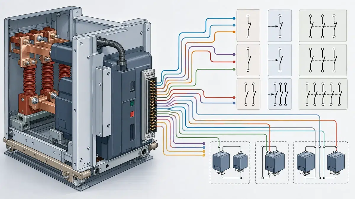
La asignación de contactos auxiliares del VCB para SCADA no consiste simplemente en contar los contactos NO y NC disponibles. En un interruptor automático de vacío, los contactos auxiliares pueden estar vinculados al mecanismo de accionamiento, al eje del interruptor, al circuito de señalización de disparo, al pulsador mecánico de cierre, al estado del conector, al enclavamiento del carro, al bloqueo de cierre o a otras funciones seleccionadas. La asignación correcta depende del diagrama de cableado aprobado del interruptor, del paquete de accesorios seleccionado y de la separación necesaria entre la señalización de SCADA, la lógica del relé de protección y los circuitos de enclavamiento.
En proyectos con VCB, el enfoque más seguro es tratar cada contacto auxiliar como una señal funcional con origen, tiempo de respuesta esperado, función y destino definidos. La documentación de ABB y Schneider muestra que los contactos auxiliares dependen del producto, su configuración y su función; por ello, el plan de asignación debe confirmarse con los planos del fabricante antes de las pruebas de aceptación en fábrica, el cableado en campo o la puesta en servicio.
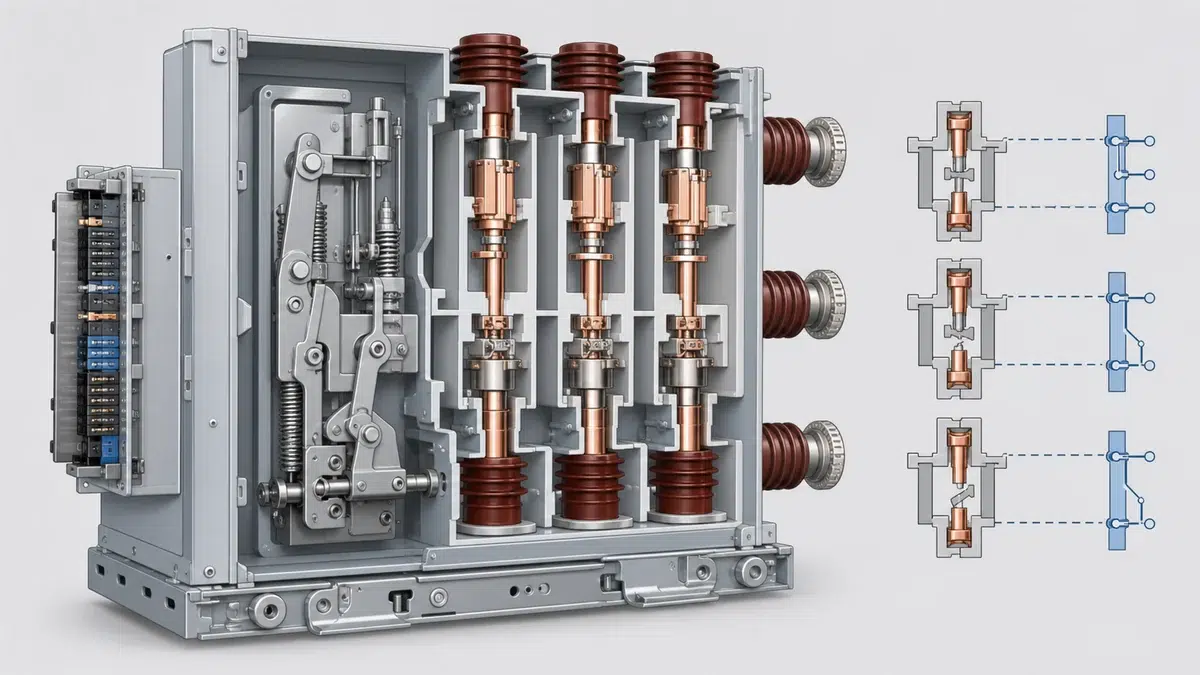
En un VCB suele haber varios sistemas que requieren contactos auxiliares: SCADA necesita indicaciones remotas de abierto y cerrado; los relés de protección pueden necesitar el estado del interruptor para la lógica o los registros de perturbaciones; los circuitos de enclavamiento pueden requerir señales de permiso o bloqueo; y los circuitos de control local quizá ya utilicen contactos dentro del esquema del interruptor.
Si estas necesidades no se asignan de forma deliberada, el proyecto puede terminar con señales duplicadas, falta de retroalimentación, alarmas molestas o modificaciones inseguras en los circuitos de cierre y disparo. El riesgo aumenta cuando el interruptor es extraíble, tiene carga de resortes motorizada, es de accionamiento eléctrico o incluye enclavamientos opcionales y contactos de estado del conector.
La expresión «contacto auxiliar del interruptor» también puede ocultar diferencias importantes. La documentación VD4X de ABB distingue entre interruptores auxiliares del mecanismo, interruptores auxiliares del eje, contactos de indicación de disparo, interruptores auxiliares del pulsador mecánico de cierre y contactos opcionales de enclavamiento. Esta distinción importa porque cada tipo representa una condición física o eléctrica diferente. Un contacto de abierto/cerrado accionado por el eje no equivale a un contacto de indicación de disparo, y ninguno debe considerarse automáticamente un contacto libre para SCADA. El manual de instrucciones ABB VD4X es la fuente principal del requisito específico del producto indicado aquí. Un resultado anormal de cierre o disparo debe documentarse en la lista de comprobación de fallos de cierre/disparo del VCB en vez de descartarse como un defecto genérico.
El proceso de asignación debe comenzar con el diagrama de circuitos aprobado por el fabricante, no con una lista genérica de bornes. El manual SecoVac de ABB muestra un interruptor auxiliar 52 dentro del circuito de cierre y enclavamiento, e identifica funciones como el bloqueo de cierre y el enclavamiento del carro. Esto ilustra una regla práctica: algunos contactos auxiliares ya pueden formar parte del diseño de control y enclavamiento propio del interruptor.
Antes de asignar contactos a SCADA o a los relés de protección, confirme:
Esto evita un error de diseño habitual: considerar libres todos los contactos que aparecen en el diagrama. Un contacto puede figurar en el circuito y, aun así, estar reservado para el bloqueo de cierre, la lógica de posición del carro o un enclavamiento diseñado por el fabricante.
SCADA y los relés de protección suelen solicitar información similar, pero no siempre necesitan la misma señal. SCADA suele requerir indicaciones remotas fiables, como interruptor abierto, interruptor cerrado, alarma de disparo, resortes cargados, estado local/remoto o posición del carro cuando esté disponible. Los relés de protección pueden necesitar el estado del interruptor para la lógica de fallo de interruptor, la supervisión del recierre, el registro de perturbaciones, los enclavamientos o las interfaces de supervisión del circuito de disparo.
Cuando la cantidad de contactos lo permita, evite compartir un único contacto seco entre varios sistemas, salvo que el diseño aprobado lo permita expresamente mediante relés intermedios, módulos de aislamiento o un esquema de bornes definido. Los circuitos compartidos pueden complicar la resolución de fallos, exponer el sistema a fallos a tierra o provocar interacciones imprevistas entre las tarjetas de entrada de SCADA y las entradas binarias del relé.
Un orden práctico de asignación es:
Este orden no es una especificación universal, sino una disciplina de diseño. La asignación final debe corresponder al modelo del VCB, los accesorios seleccionados, la disposición del conector secundario y la filosofía de cableado del proyecto. Utilice la Gama de disyuntores de vacío XBRELE para evaluar los equipos disponibles frente a las condiciones de servicio del proyecto antes de solicitar una configuración definitiva.
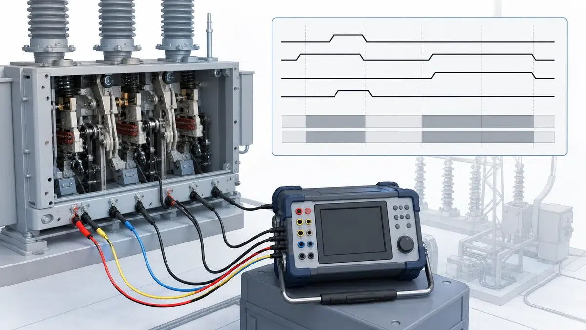
La tabla de asignación de contactos del VCB debe identificar el origen de cada señal, no solo su destino. Por ejemplo, una señal de posición del interruptor puede proceder de un interruptor auxiliar del mecanismo o de un interruptor auxiliar del eje, según el diseño. Un contacto de indicación de disparo puede señalar que se produjo un disparo, pero no debe suponerse equivalente a la posición de interruptor abierto, a menos que el diagrama de cableado y la descripción de funcionamiento confirmen esa función.
La documentación EvoPacT de Schneider describe un conector secundario estándar y un conector opcional Contact Plus, que puede proporcionar contactos auxiliares adicionales del interruptor e indicación del estado del conector. También señala que la capacidad de contactos depende de la configuración del producto. Esto es importante para ingeniería y compras: puede ser posible añadir contactos, pero no es una garantía genérica. Depende de la configuración solicitada.
Para cada contacto, el plan debe indicar:
Este formato reduce la ambigüedad durante las pruebas FAT y SAT, porque el equipo de pruebas puede verificar el contacto por su función y no solo por continuidad. Utilice la guía de verificación FAT/SAT del interruptor para mantener la trazabilidad de las evidencias de fábrica y de campo durante la entrega.
La asignación de contactos auxiliares no debe interferir con el circuito de cierre del fabricante. Schneider advierte que los contactos auxiliares propios del interruptor no deben cablearse en serie con el disparador de cierre y el contacto de cierre, ya que esto puede anular el sistema mecánico antip bombeo. Esta advertencia debe tratarse como un límite de diseño.
La protección antip bombeo está diseñada para evitar intentos repetidos de cierre bajo ciertas condiciones de una orden de cierre mantenida. Si el cableado de campo altera la relación entre la orden de cierre, el disparador de cierre y los contactos auxiliares del interruptor, el comportamiento de protección original puede verse comprometido. Por tanto, los permisos de cierre de SCADA, las órdenes de cierre del relé y los circuitos de cierre local deben implementarse según el esquema de control aprobado, en lugar de añadir lógica improvisada de contactos auxiliares en serie con el circuito de la bobina de cierre.
Esto es especialmente relevante cuando una instalación desea añadir supervisión de control remoto después de que ya se haya suministrado el equipo de maniobra. La solución adecuada no es «buscar un contacto libre» e insertarlo en el circuito de cierre. La solución adecuada consiste en revisar el diagrama de control del fabricante, confirmar la interfaz de cierre remoto permitida y actualizar el plano mediante un cambio de ingeniería aprobado.
Los VCB extraíbles pueden incluir funciones de posición del carro, estado del conector, bloqueo de cierre y enclavamiento. Pueden parecer señales útiles para SCADA, pero también pueden formar parte de la lógica de seguridad y funcionamiento. Por ejemplo, la documentación SecoVac de ABB identifica funciones de bloqueo de cierre y enclavamiento del carro, lo que demuestra por qué estos circuitos deben tratarse como enclavamientos de ingeniería y no como simples puntos de señalización.
Si SCADA necesita la posición de servicio/prueba del carro, el estado del conector secundario o la indicación de bloqueo de cierre, confirme si esas señales están disponibles en contactos de indicación específicos o si están integradas en un circuito de enclavamiento. No conecte circuitos de supervisión en paralelo a los contactos de enclavamiento sin comprobar la capacidad nominal del contacto, la tensión del circuito, el aislamiento y las indicaciones del fabricante. Para comprobar los valores nominales, compare estas condiciones con la guía de valores nominales de disyuntores de vacío.
La asignación también debe distinguir entre el estado de permiso y el estado de alarma. «Conector conectado», «carro en posición de servicio» y «cierre no bloqueado» no son términos intercambiables. Cada uno comunica algo distinto al operador o a la lógica del relé. Etiquetar mal estos puntos puede producir mímicos incorrectos en SCADA o permisos engañosos para el control remoto.
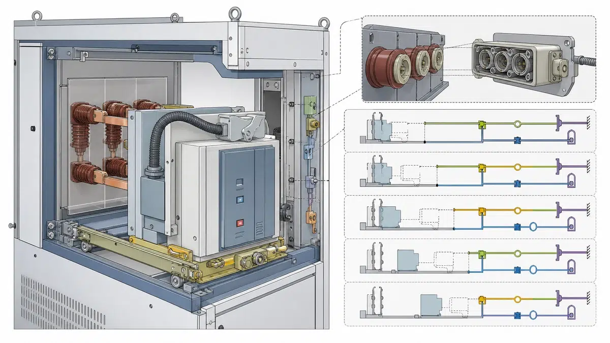
La matriz de asignación de contactos es el documento central para asignar los contactos auxiliares del VCB. Debe relacionar el diagrama unifilar, el esquema de control, la lista de entradas/salidas de SCADA y el diagrama de lógica del relé. La matriz no necesita inventar especificaciones nuevas; organiza los contactos disponibles del fabricante y las funciones requeridas por el proyecto.
Una matriz útil incluye estas columnas:
| Artículo | Origen del contacto | Función | Referencia del estado normal | Destino | Uso | Referencia del plano |
|---|---|---|---|---|---|---|
| 1 | Interruptor auxiliar del interruptor | Indicación de interruptor cerrado | Según el diagrama del fabricante | Relé de protección | Lógica/estado | Esquema aprobado |
| 2 | Interruptor auxiliar del interruptor | Indicación de interruptor abierto | Según el diagrama del fabricante | RTU de SCADA | Indicación remota | Esquema aprobado |
| 3 | Contacto de indicación de disparo | Indicación de evento de disparo | Según el diagrama del fabricante | Relé o SCADA | Alarma/evento | Esquema aprobado |
| 4 | Contacto de estado del conector, si se suministra | Indicación del conector secundario | Según el diagrama del fabricante | SCADA | Mantenimiento/estado | Esquema aprobado |
| 5 | Contacto de enclavamiento, si se suministra | Permiso o estado de bloqueo de cierre | Según el diagrama del fabricante | Circuito de control o monitor | Enclavamiento/estado | Esquema aprobado |
La expresión «si se suministra» es esencial. El conector opcional Contact Plus de Schneider y los contactos de enclavamiento opcionales de ABB muestran que la disponibilidad de contactos auxiliares depende de la configuración solicitada. Por ello, la matriz debe comprobarse con la placa de características, el diagrama de cableado, la disposición del conector y la lista de accesorios del interruptor real.
Las pruebas de aceptación en fábrica y en campo deben verificar tanto el funcionamiento del contacto como el significado de la señal. No basta con confirmar que una entrada binaria cambia de estado. La prueba debe confirmar que la señal cambia ante la condición mecánica o eléctrica correcta.
Entre las comprobaciones recomendadas se incluyen:
Cualquier discrepancia debe resolverse mediante una revisión del plano y la aprobación de ingeniería, no mediante cambios de bornes sin documentar.
La asignación de contactos auxiliares del VCB es el proceso de asignar cada contacto auxiliar disponible del interruptor a una finalidad definida, como la señalización de SCADA, la lógica del relé de protección, la indicación de disparo, el estado del conector o el enclavamiento. La asignación debe basarse en el diagrama de cableado aprobado por el fabricante y en la configuración real del interruptor.
La mejor manera es reservar primero los contactos necesarios para los circuitos propios de control y enclavamiento del interruptor y, después, asignar a SCADA los contactos disponibles confirmados para puntos como abierto, cerrado, indicación de disparo y estado del conector, cuando se suministre. SCADA no debe utilizar contactos que ya formen parte de la lógica de cierre, disparo, bloqueo de cierre o enclavamiento del carro.
El estado del interruptor suele indicar su posición actual, abierto o cerrado. La indicación de disparo es un evento o condición independiente que señala que se produjo una operación de disparo, si ese contacto está incluido en la configuración seleccionada. La documentación VD4X de ABB distingue los contactos de indicación de disparo de otros tipos de interruptores auxiliares, por lo que no debe suponerse que ambas señales significan lo mismo.
El cableado de campo puede interferir con el diseño de cierre y antip bombeo del fabricante. Schneider advierte específicamente que los contactos auxiliares propios del interruptor no deben cablearse en serie con el disparador de cierre y el contacto de cierre, ya que eso puede anular el sistema mecánico antip bombeo.
Los conectores opcionales de contactos auxiliares pueden ampliar las señales disponibles o proporcionar indicaciones de estado adicionales, según la configuración del producto. La documentación EvoPacT de Schneider describe un conector secundario estándar y un conector Contact Plus opcional que puede proporcionar contactos auxiliares adicionales del interruptor e indicación del estado del conector; también deja claro que la capacidad de contactos depende de la configuración.
Por tanto, asignar contactos auxiliares del VCB para SCADA y los relés de protección es una tarea de ingeniería controlada. Comienza con el diagrama de circuitos aprobado del interruptor, respeta las funciones definidas por el fabricante, separa las necesidades de SCADA y protección cuando sea práctico, evita cambios no autorizados en el circuito de cierre y verifica cada señal durante FAT y SAT.