¿Necesita las especificaciones completas?
Descargue nuestro Catálogo de productos 2025 para obtener planos detallados y parámetros técnicos de todos los componentes de los equipos de conmutación.
Obtener catálogo
Descargue nuestro Catálogo de productos 2025 para obtener planos detallados y parámetros técnicos de todos los componentes de los equipos de conmutación.
Obtener catálogo Descargue nuestro Catálogo de productos 2025 para obtener planos detallados y parámetros técnicos de todos los componentes de los equipos de conmutación.
Obtener catálogo
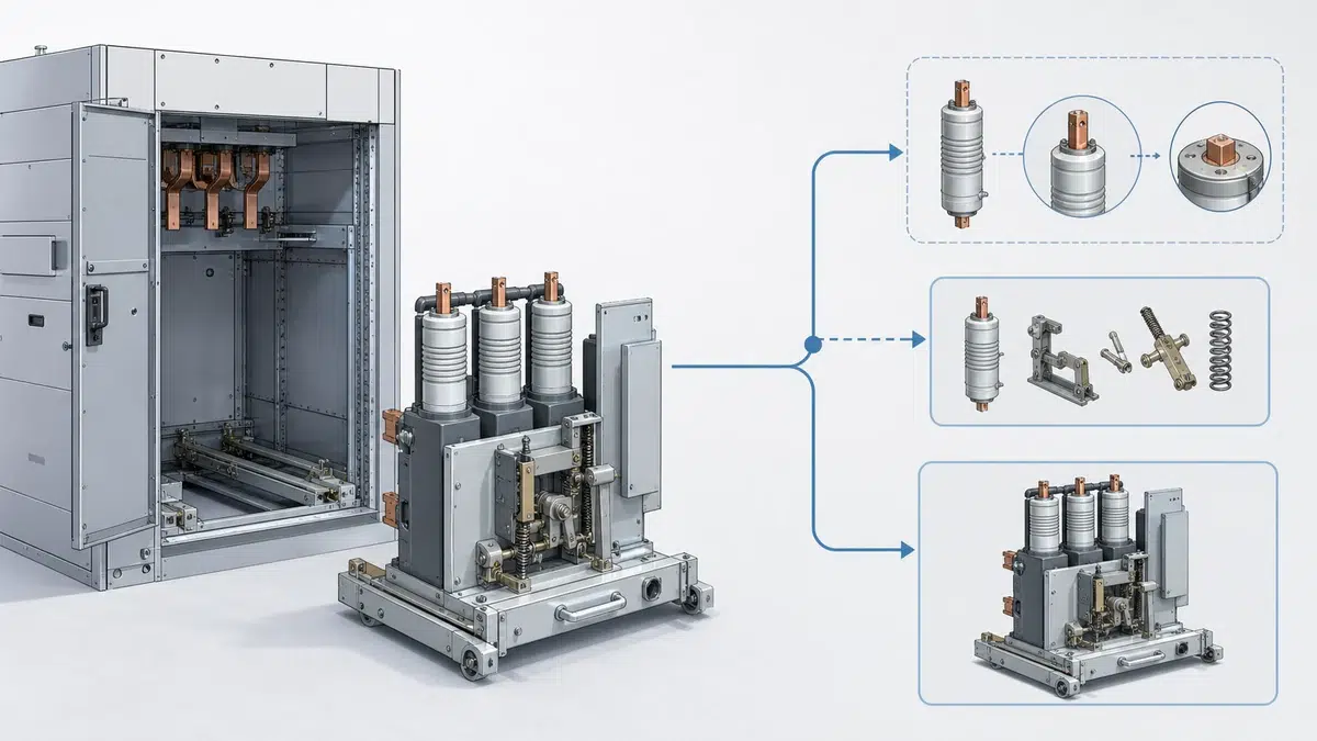
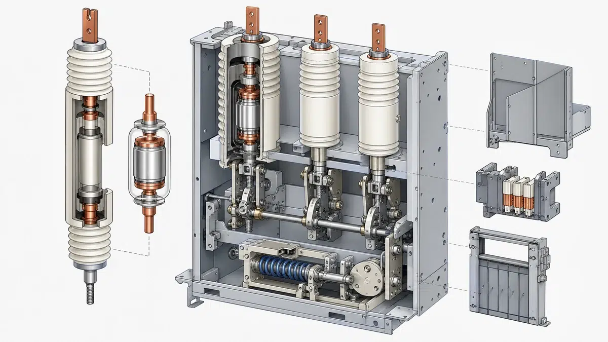
Medium-voltage vacuum circuit breakers protect distribution networks by interrupting fault currents inside a near-perfect vacuum sealed within a ceramic or glass envelope commonly called the vacuum bottle or vacuum interrupter. Alongside the vacuum interrupter, the arc chute assembly—though functionally absent in the same form as in air-break or oil breakers—is represented in VCB design by the interrupter housing, shield geometry, and exhaust baffling that manage residual dielectric recovery. When either component degrades, the breaker's ability to safely clear a fault is compromised, and a structured replacement decision is necessary. This article presents a practical decision matrix that engineers, maintenance planners, and asset managers can apply to determine whether arc chute components, vacuum bottles, or entire pole assemblies should be refurbished, replaced, or escalated to the original equipment manufacturer.
—
Unlike oil or SF₆ breakers, where the interrupting medium is replenished or recirculated, the vacuum inside a VCB interrupter is sealed for life at manufacture. Every contact separation during normal switching or fault interruption erodes the contact material, deposits metallic vapor on the shield, and incrementally reduces the vacuum level. This sealed, consumable nature means that the bottle has a finite useful life expressed in terms of cumulative interrupted current, number of mechanical operations, or both.
Manufacturers translate these physical limits into documented operating limits specific to each product family. ABB, for instance, specifies that a VCB pole and its vacuum interrupter are maintained up to the product-specific permitted operating limits; once a relevant limit is reached, complete poles may require replacement, and that replacement must be performed by ABB or specifically trained personnel because precise contact-gap and over-travel adjustments are required afterward (ABB VD4 40.5 kV IOM Manual). This requirement for post-replacement adjustment is a crucial differentiator: replacing a vacuum bottle is not plug-and-play.
Contact erosion is the primary wear mechanism. Most manufacturers provide a contact-wear indicator—a visible reference mark on the operating rod or pole front—that signals when the minimum allowable contact gap has been consumed. When this indicator reaches the reject mark, replacement is mandatory regardless of how the vacuum integrity appears on a Hi-Pot or vacuum integrity test.
—
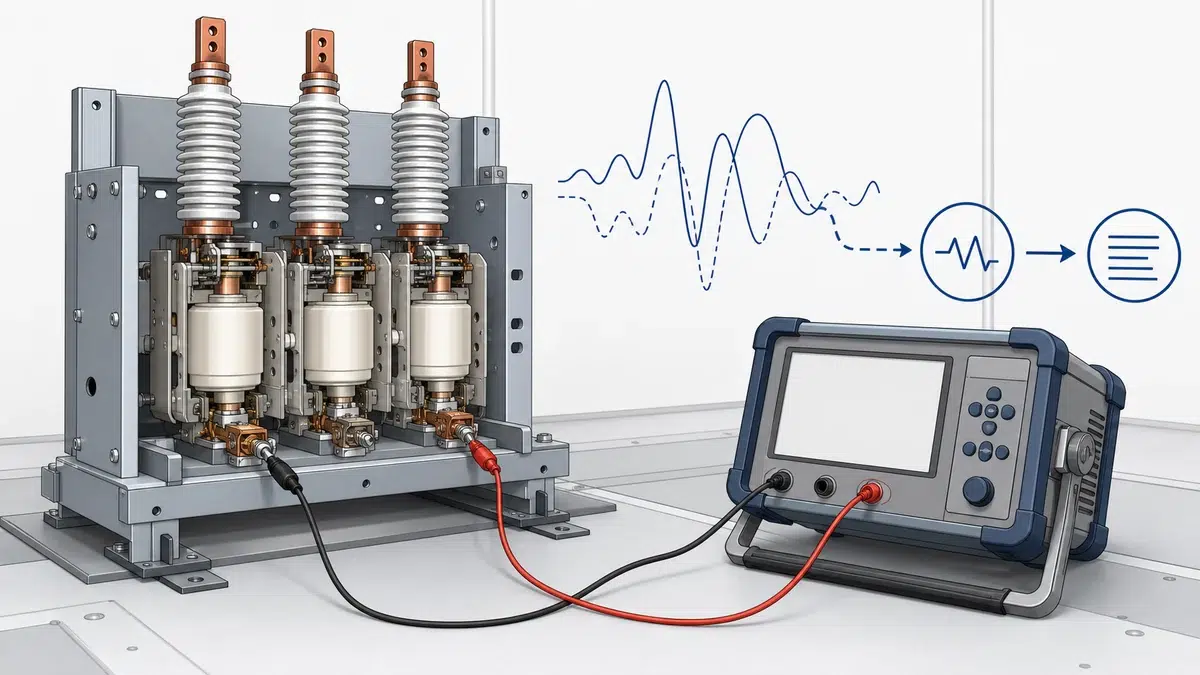
The term "arc chute" in a VCB context is often misapplied. True arc chutes with de-ionizing plates exist in air-break breakers. In a VCB, the functional equivalent is the internal arc shield inside the vacuum interrupter, which catches metallic condensate from the arc plasma and prevents it from depositing on the ceramic envelope where it would degrade the external flashover voltage. Externally, some VCB designs include a terminal shroud or insulating boot that directs any post-arc gas discharge away from live parts. Use the portafolio de VCB de XBRELE para evaluar los equipos disponibles frente a las condiciones de servicio del proyecto antes de solicitar una configuración definitiva.
Deterioration indicators for these arc management components differ from vacuum bottle indicators:
Because the internal shield is not a field-replaceable part on sealed interrupters, its degradation is managed indirectly through current-based operating limits rather than direct inspection.
—
A replacement decision matrix consolidates quantitative measurements, qualitative observations, and manufacturer policy rules into an unambiguous go/no-go outcome. The matrix below operates on six primary inputs.
**Input 1 — Contact Wear Indicator (CWI) reading**
Record the indicator position in millimeters or as a fraction of the total allowable wear band. When CWI ≥ 100 % of the allowable band, replacement is mandatory. When CWI is between 80 % and 99 %, schedule replacement at the next planned outage. Below 80 %, no bottle action is required on this criterion alone.
**Input 2 — Cumulative fault-interrupted current (kA symmetrical)**
Compare the sum of all fault interruptions against the rated short-circuit making and breaking capacity and the manufacturer's cumulative duty table. ABB publishes per-interruption duty ratings that decrement from a total allowable budget. Exceeding this budget triggers the same mandatory-replacement outcome as a worn CWI. For the rated-data check, compare these conditions with the guía de selección de valores nominales del interruptor.
**Input 3 — Mechanical operation count**
VCBs carry a rated mechanical endurance, typically 10,000 to 30,000 operations depending on current rating. The electronic operations counter or relay log provides this figure. Exceeding mechanical endurance triggers pole or full mechanism inspection and may require factory overhaul regardless of vacuum integrity.
**Input 4 — Vacuum integrity test result**
A Hi-Pot (power-frequency withstand) test or a dedicated vacuum tester applies voltage across the open contacts inside the bottle. A pass result demonstrates adequate vacuum; a fail result is an absolute mandatory-replacement trigger. However, a pass result does not override wear-based limits—a bottle can hold vacuum and still be condemned on contact erosion grounds.
**Input 5 — Visual condition of external insulation, arc chute shroud, and terminal boots**
Any carbon tracking, cracking beyond minor surface crazing, or deformation is a conditional-replacement trigger. The severity rating (minor/moderate/severe) determines whether replacement can be deferred to a planned window.
**Input 6 — Manufacturer product-series replacement policy**
This input overrides all others. Some manufacturers restrict vacuum interrupter replacement to factory service or do not supply the interrupter as a spare part at all. Schneider's documented policy for certain VCB ranges does not permit vacuum interrupters to be replaced as separate spare parts, meaning the correct response to bottle failure in those series is full pole or full unit replacement (Schneider Electric FAQ FA178928). Always verify the applicable policy before ordering components.
| Input | Threshold: Immediate Replacement | Threshold: Planned Replacement | Monitor Only |
|---|---|---|---|
| CWI reading | ≥ 100 % of band | 80–99 % of band | < 80 % |
| Fault-interrupted current | Exceeds cumulative budget | Within 20 % of budget | > 20 % remaining |
| Mechanical operations | Exceeds rated endurance | Within 10 % of endurance | > 10 % remaining |
| Prueba de integridad al vacío | Fracaso | N/A (test is pass/fail) | Pase |
| External insulation condition | Severe tracking or cracking | Degradación moderada | Minor surface marks |
| Manufacturer policy | No field replacement permitted | Factory-trained only | Standard trained crew |
When any single input falls in the "Immediate Replacement" column, the breaker must be withdrawn from service pending component action. Multiple "Planned Replacement" indicators in the same inspection round should be consolidated into a single outage to minimize total asset downtime.
—
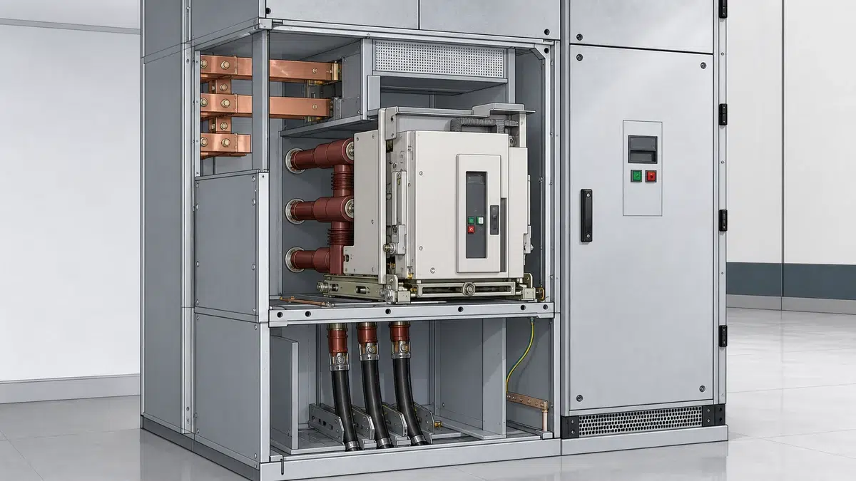
No replacement activity—whether vacuum bottle, pole assembly, insulating shroud, or contact-alignment adjustment—may begin without establishing a full safe-work envelope. ABB's documentation is explicit: repair work requires isolation from all supply sides, securing against reclosing, and complete discharge of all stored energy in the spring operating mechanism (ABB VD4 63 Manual). Stored energy in a charged spring mechanism is a serious mechanical hazard; manual discharge via the dedicated pushbutton or screw procedure must be verified before any pole cover is removed.
Electrical isolation prerequisites include:
– Confirmed open position of the breaker and any upstream and downstream disconnects
– Lock-out/tag-out applied to all control voltage supplies (motor, trip coil, closing coil)
– Earthing applied to all three phases on both sides of the breaker as required by the site safety rules
– Confirmation that auxiliary heaters and anti-condensation circuits are isolated
After energy isolation, the specific product documentation must be followed for disassembly sequence. Incorrect disassembly can preload or distort the operating linkage such that post-replacement contact-gap measurements are inaccurate.
Additionally, ABB specifies that vacuum testing and repair must follow product documentation and qualified-person requirements. This means the technician performing the work must hold documented competency in the specific product family—a general electrical qualification is necessary but not sufficient. Sites that do not retain such competency internally must engage the manufacturer's field service team.
—
Contact gap and contact over-travel (wipe) are set during manufacture and must be re-established after any vacuum interrupter replacement. Contact gap is the open-position separation between the fixed and moving contacts; it determines the dielectric withstand of the open pole. Over-travel is the additional travel of the operating rod after the contacts first touch on closing; it loads the contact spring and determines contact force, which directly affects the thermal and dynamic current-carrying capacity. An abnormal close or trip result should be carried into the guía de resolución de fallos de cierre/apertura del interruptor en vez de descartarse como un defecto genérico.
Correct adjustment requires:
– A calibrated depth gauge or feeler gauge of the type specified in the product manual
– The specific go/no-go dimensions published for that product series at the rated voltage class
– Functional close-open cycle tests under controlled conditions to verify mechanical endurance spring energy is correctly calibrated
– A final vacuum integrity test on the replacement bottle before the breaker is returned to service
Because these adjustments interact with the mechanism timing, manufacturers such as ABB restrict pole replacement to factory or specifically trained personnel. Sites that attempt bottle replacement without trained personnel risk installing a breaker with incorrect contact force that fails under rated fault current even though it passes a routine vacuum integrity test.
—
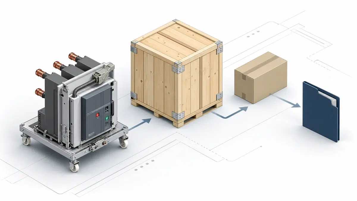
A replacement decision should generate a formal record that feeds the asset management system. The minimum data set for each replaced component is:
This record serves two purposes. First, it provides the baseline for the next replacement-interval projection—if the previous bottle lasted eight years and 2,400 operations under a known loading profile, the replacement interval for the new bottle can be scheduled accordingly. Second, it satisfies audit requirements and supports warranty claims if the replacement component fails prematurely. Use the lista de comprobación de aceptación FAT y SAT del VCB para mantener la trazabilidad de las evidencias de fábrica y de campo durante la entrega.
When the decision matrix output is "no field replacement permitted" due to manufacturer policy, the record should document the OEM engagement, the work order reference issued by the manufacturer, and any updated maintenance schedule provided by the OEM service team.
—
The contact wear indicator (CWI) is the most accessible primary indicator. It is a mechanical reference mark on the operating rod or pole face that shows cumulative contact erosion. When the indicator reaches the manufacturer's rejection mark, the vacuum interrupter has consumed its allowable contact material and must be replaced regardless of whether it passes a vacuum integrity test. Some product families also track cumulative fault-interrupted current and decrement a duty budget; exhausting that budget is an equally binding replacement trigger. Both the CWI and the duty budget must be monitored in parallel because a breaker that has experienced few operations but several high-magnitude fault interruptions may exhaust its duty budget while the CWI still reads acceptable.
Replacing only the vacuum interrupter (bottle) requires removing the sealed interrupter from the operating linkage, installing the new bottle, and then precisely re-adjusting contact gap and over-travel to the manufacturer's specifications. Replacing a complete pole assembly means removing the entire pre-assembled pole unit—interrupter, housing, operating linkage, and terminal hardware—and substituting a factory-set replacement that requires only mechanical connection to the drive shaft and electrical connection to the busbars. Complete pole replacement is generally faster, reduces the risk of incorrect adjustment, and is the only option for product series where the interrupter is not available as a separate spare part. ABB's documentation for certain product families specifies complete pole replacement as the standard corrective action once operating limits are reached, performed by ABB or specifically trained personnel because post-installation adjustment is still necessary even with a pole-level replacement.
Manufacturer policy can make all other decision-matrix inputs secondary by restricting the available corrective action. Schneider Electric's published policy for certain VCB ranges states that vacuum interrupters are not available as separate spare parts, meaning a field technician cannot simply order a bottle and swap it. In those series, the correct response to a bottle failure or end-of-life condition is full pole or full unit replacement, and that work must be coordinated through the manufacturer's service channel. Ignoring this policy and attempting a field bottle replacement with a non-OEM part creates liability exposure, may void any remaining warranty, and risks incorrect contact adjustment because third-party bottles may have different stem lengths or contact spring pre-loads. Before any replacement decision reaches the procurement stage, the applicable product-series policy must be confirmed through the manufacturer's documentation or service team.
ABB's repair documentation establishes the essential sequence: the breaker must be fully isolated from all supplies on both the line and load sides; it must be secured against reclosing through lock-out/tag-out on both the mechanical operating mechanism and all control voltage circuits; and all stored energy in the spring mechanism must be discharged before any mechanical disassembly begins. Stored spring energy can release suddenly if the mechanism is disturbed during disassembly, creating a severe crush or impact hazard. Earthing must be applied per site safety rules before any physical contact with pole components. After energy isolation is confirmed, the specific product manual governs disassembly sequence, torque values, and reinstallation steps. ABB also specifies that vacuum testing and all repair activities must follow product documentation and be carried out by qualified persons, meaning general electrical authorization is necessary but product-specific competency must also be demonstrated and documented before work commences.
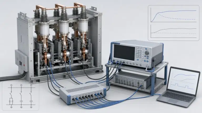
Post-replacement testing validates that the new vacuum bottle holds adequate vacuum, that contact gap and over-travel are within specification, and that the complete mechanism operates correctly before the breaker is exposed to system voltage and potential fault current. The minimum test sequence includes a vacuum integrity test (Hi-Pot or equivalent) on the replacement bottle at the voltage level specified by the product manual, dimensional measurement of contact gap and over-travel with a calibrated gauge, and a series of close-open operations to confirm mechanism timing and verify that the operations counter and contact wear indicator have been reset or baselined correctly. On digital protection relays, the trip and close coil current traces from the test operations should be captured and compared against the manufacturer's reference envelopes, because an out-of-specification spring charge or latching adjustment will manifest as a deviating coil current profile before it causes an in-service failure.