Need Full Specifications?
Download our 2025 Product Catalog for detailed drawings and technical parameters of all switchgear components.
Get CatalogDownload our 2025 Product Catalog for detailed drawings and technical parameters of all switchgear components.
Get CatalogDownload our 2025 Product Catalog for detailed drawings and technical parameters of all switchgear components.
Get Catalog
Gas-insulated switchgear (GIS) and air-insulated switchgear (AIS) solve the same problem—isolating and interrupting medium-voltage circuits—through fundamentally different means. The insulation medium you choose determines clearances, interface design, maintenance burden, and total cost of ownership. This comparison cuts through marketing claims to examine what actually changes when SF₆ replaces air as your primary dielectric.
The core distinction is straightforward: AIS uses atmospheric air at ~101 kPa; GIS uses pressurized SF₆ at 0.3–0.5 MPa absolute. Everything else follows from this single decision.
Air-Insulated Switchgear Construction
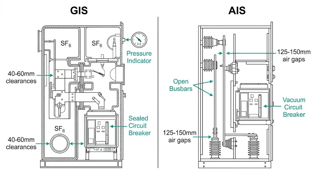
AIS relies on physical separation between conductors. For 12 kV systems, minimum phase-to-phase clearances run 125–150 mm to achieve adequate dielectric strength—air provides roughly 3 kV/mm under dry conditions. Humidity, altitude, and contamination erode this margin.
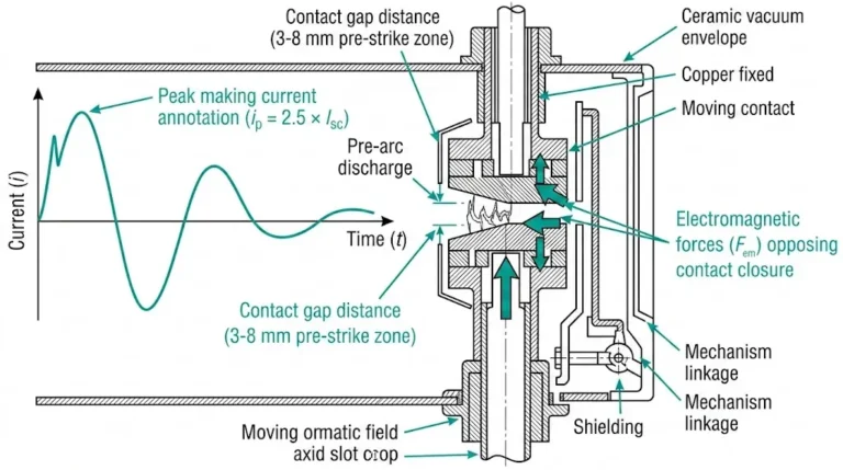
The vacuum circuit breaker handles current interruption within a sealed chamber, while surrounding air provides phase-to-ground and phase-to-phase insulation. This functional separation—vacuum for interruption, air for insulation—defines AIS architecture.
Gas-Insulated Switchgear Construction
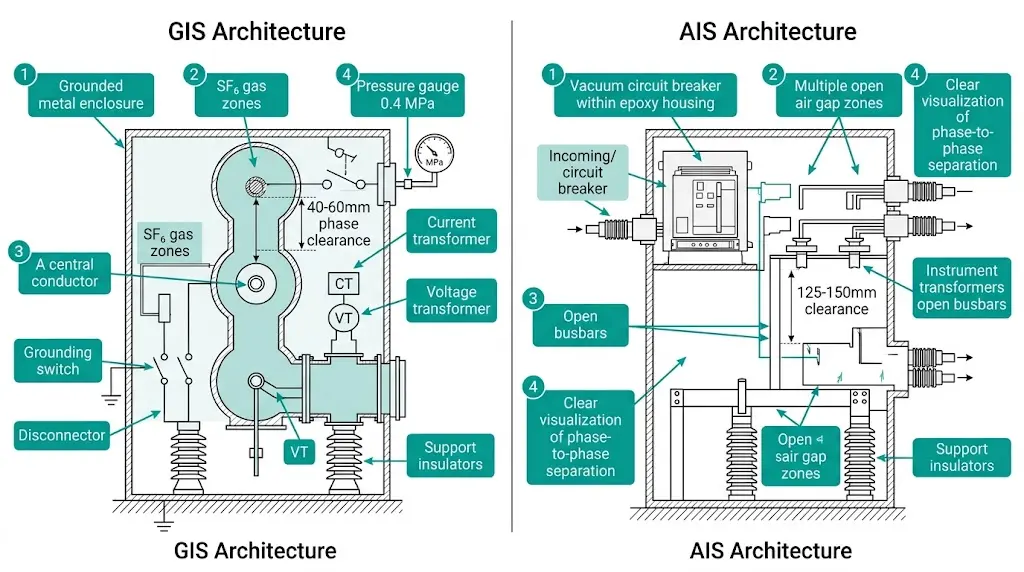
GIS houses all live components within grounded metal enclosures filled with SF₆. The gas serves dual functions: primary insulation and arc-quenching medium. SF₆ delivers approximately 8.5–9 kV/mm dielectric strength at 0.4 MPa—nearly three times air’s capability.
This performance gap enables phase clearances of 40–60 mm at 12 kV. The result: 50–70% footprint reduction compared to equivalent AIS installations.
The Trade-Off
Compactness comes at a cost. GIS requires sealed compartments, gas-handling infrastructure, and specialized maintenance procedures. AIS allows visual inspection and straightforward component access. Neither approach is universally superior—project conditions determine the right choice.
Insulation design represents the sharpest technical divergence between these technologies.
| Parameter | AIS (Air) | GIS (SF₆ at 0.4 MPa) |
|---|---|---|
| Dielectric strength | ~3 kV/mm | ~8.5 kV/mm |
| Phase clearance (12 kV) | 125–150 mm | 40–60 mm |
| Pressure dependency | None | Critical |
| Contamination sensitivity | High | Low (sealed) |
AIS clearances must accommodate worst-case atmospheric conditions. Field experience across Southeast Asian industrial facilities shows humidity alone can reduce air-gap breakdown voltage by 10–15% during monsoon seasons.
GIS performance depends on maintaining gas density. A slow leak dropping pressure from 0.4 MPa to 0.25 MPa reduces dielectric withstand by 25–30%. Density monitoring with alarm at 90% and lockout at 85% of rated pressure is standard practice.
GIS assemblies incorporate epoxy resin insulators with specific creepage requirements, typically ≥ 25 mm/kV for indoor applications. These solid insulators must withstand continuous SF₆ pressure while maintaining dielectric integrity across temperature cycles from −25°C to +55°C ambient conditions.
AIS designs use cast resin or porcelain insulators exposed to ambient air. Surface contamination directly impacts flashover voltage, demanding creepage distances of 31–42 mm/kV based on pollution severity per IEC 60815. Coastal and industrial sites routinely require the upper range.
[Expert Insight: Insulation Coordination in Practice]
- GIS allows tighter design margins (5–15% above minimum) because sealed environments eliminate atmospheric variables
- AIS engineers typically build 20–40% buffers into clearance calculations to accommodate degradation over 25-year service life
- Partial discharge acceptance: GIS specifications commonly require <5 pC; AIS often omits PD testing at MV levels due to corona masking
- Altitude affects AIS only—GIS maintains rated performance at 3,000+ meters without derating
Where conductors enter and exit the switchgear, design philosophies diverge sharply.
AIS approach: Stress-cone or elbow-type terminations with generous air clearances. Installation tolerances of ±5–10 mm are typical. Outdoor-rated accessories required for exposed environments. Switchgear components like wall bushings use porcelain or composite housings sized for pollution-class creepage requirements.
GIS approach: Gas-tight plug-in terminations with O-ring seals. Tolerances tighten to ±1–2 mm—misalignment that causes minor concern in AIS can prevent gas-tight sealing in GIS. These interfaces must maintain integrity across 30-year service life and thousands of thermal cycles.
| Interface Element | AIS | GIS |
|---|---|---|
| Bushing type | Porcelain/composite, external creepage | SF₆-sealed plug-in |
| Creepage requirement | 16–31 mm/kV (pollution-dependent) | Minimal (internal to gas zone) |
| Installation tolerance | ±5–10 mm | ±1–2 mm |
| Maintenance access | Direct visual inspection | Requires compartment isolation |
Field data from petrochemical installations indicates bushing interface integrity accounts for approximately 15% of GIS maintenance interventions—primarily O-ring degradation and connector torque relaxation.
[FIG-02: Detailed comparison of AIS elbow termination with stress cone versus GIS gas-tight plug-in bushing. Show O-ring locations, creepage paths, and critical alignment dimensions. XBRELE teal #00A699 callouts.]
Both technologies predominantly use vacuum interrupters for current interruption at medium voltage. The arc extinction mechanism—contact separation in high vacuum (10⁻⁴ Pa)—remains identical. What differs is external insulation.
In AIS: The vacuum interrupter sits within an epoxy-resin or porcelain housing. Air provides phase-to-phase and phase-to-ground insulation around the assembly.
In GIS: The same vacuum interrupter mounts within an SF₆-filled compartment. The gas handles external phase insulation while vacuum handles arc extinction.
Testing across mining applications with frequent load switching revealed:
However, GIS maintains consistent performance from -40°C to +55°C. AIS outdoor installations require derating in extreme cold—contact mechanism lubricants stiffen, increasing operating time.
SF₆’s arc-quenching capability provides backup. If a vacuum interrupter develops internal issues, the surrounding gas can suppress incipient faults that might propagate in air-insulated designs.
This table captures the specification shifts engineers encounter when switching between technologies:
| Specification | AIS Typical | GIS Typical |
|---|---|---|
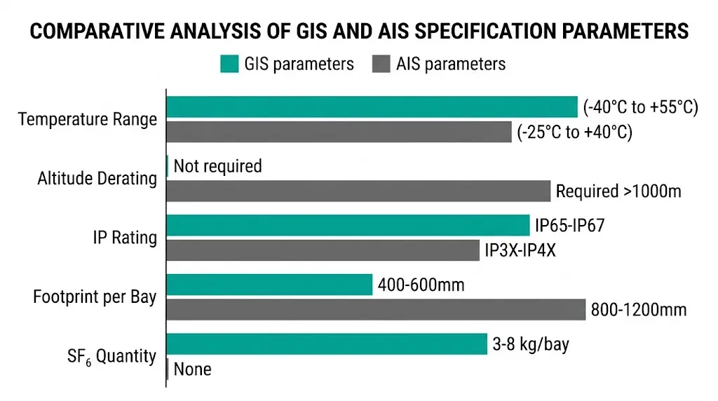
| Ambient temperature | -25°C to +40°C | -40°C to +55°C |
| Altitude derating | Required >1,000 m | Not required |
| Pollution class | Must specify (I–IV) | N/A (sealed) |
| IP rating | IP3X–IP4X | IP65–IP67 |
| Footprint per bay (12 kV) | 800–1,200 mm | 400–600 mm |
| Weight per bay (12 kV) | 300–500 kg | 400–700 kg |
| SF₆ quantity | None | 3–8 kg per bay typical |
Altitude consideration: AIS at 3,000 meters requires approximately 25% increased clearances—or acceptance of reduced BIL. GIS internal gas pressure remains independent of ambient atmosphere, maintaining full ratings without modification.
Operational burden differs substantially between technologies.
| Activity | AIS Interval | GIS Interval |
|---|---|---|
| Visual inspection | 6–12 months | Continuous monitoring |
| Contact resistance test | 2–4 years | 15–25 years (internal) |
| Insulation service | 1–5 years (cleaning) | N/A |
| Major overhaul | 10–15 years | 20–30 years |
AIS demands regular hands-on attention. Insulator cleaning frequency depends on pollution exposure—coastal installations may require annual cleaning while rural substations extend to 5-year cycles.
GIS front-loads capital cost but minimizes operational intervention. For installations with difficult access—offshore platforms, underground vaults, congested urban sites—this trade-off often justifies 40–60% higher initial pricing.
GIS specifications must address:
These requirements add procurement complexity absent from AIS specifications.
[Expert Insight: Lifecycle Cost Considerations]
- Break-even analysis typically favors GIS when maintenance access costs exceed $2,000 per intervention
- SF₆ gas replacement costs $15–25 per kg; total gas value per bay runs $50–200
- AIS contact and insulator replacement parts remain widely available from multiple sources
- GIS compartment repairs often require factory return or specialized field service teams
Project conditions—not technology preferences—should drive selection.
Modern substations increasingly combine technologies: GIS for circuit breaker and bus sections (compactness where it matters most), AIS for disconnectors and earthing switches (cost optimization on simpler functions).
Environmental pressure is reshaping GIS design. SF₆ carries a global warming potential of 23,500× CO₂, driving regulatory action—particularly under EU F-Gas Regulation.
| Alternative Medium | Dielectric vs SF₆ | Commercial Status |
|---|---|---|
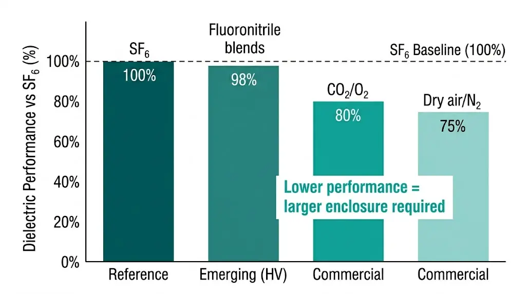
| Dry air / N₂ | 70–80% | Commercial (larger enclosures) |
| CO₂ / O₂ mixtures | 75–85% | Commercial (select manufacturers) |
| Fluoronitrile blends | 95–100% | Emerging (primarily HV) |
| Solid-insulated vacuum | Different principle | Commercial (MV) |
Specification impact: SF₆-free GIS typically requires 15–25% larger enclosures to maintain equivalent BIL ratings. Gas handling procedures also change—CO₂ mixtures need different recovery equipment than SF₆.
CIGRE Technical Brochure 602 provides comprehensive guidance on SF₆ alternative assessment for utilities evaluating transition strategies.
Whether your project specifies AIS vacuum circuit breakers for cost-effective distribution or requires components for GIS-integration, XBRELE delivers engineered solutions backed by field-proven performance.
Our vacuum circuit breaker product line serves both conventional AIS panel builders and GIS assembly manufacturers requiring qualified interrupter modules. Technical consultation available for technology selection and specification development.
Contact XBRELE for project-specific recommendations and competitive quotations.
Q: What drives the footprint difference between GIS and AIS?
A: SF₆ gas provides approximately 3× the dielectric strength of air, enabling phase clearances of 40–60 mm versus 125–150 mm at 12 kV—this clearance reduction translates directly to 50–70% smaller enclosure dimensions.
Q: Do both technologies use vacuum interrupters for arc extinction?
A: At medium voltage, yes—vacuum interrupters dominate both GIS and AIS designs for current interruption, with the surrounding insulation medium (SF₆ or air) providing phase-to-phase and phase-to-ground isolation only.
Q: How does altitude affect GIS versus AIS performance?
A: AIS requires increased clearances or accepts reduced BIL above 1,000 meters because air dielectric strength decreases with atmospheric pressure; GIS maintains full ratings at any altitude since internal gas pressure is independent of ambient conditions.
Q: What maintenance burden should I expect from each technology?
A: AIS requires visual inspection every 6–12 months and contact resistance testing every 2–4 years; GIS operates 15–25 years between internal inspections but demands continuous gas density monitoring and specialized handling equipment for any intervention.
Q: Is SF₆ being phased out of GIS designs?
A: Regulatory pressure is increasing due to SF₆’s extreme global warming potential (23,500× CO₂), with dry air, CO₂ mixtures, and fluoronitrile alternatives gaining commercial traction—though these typically require 15–25% larger enclosures for equivalent ratings.
Q: When does GIS lifecycle cost become competitive with AIS?
A: GIS typically achieves cost parity over 20–25 years when maintenance access is difficult or expensive (underground vaults, offshore platforms, congested urban sites) or when pollution-related insulator failures would otherwise drive frequent AIS service interventions.