Need Full Specifications?
Download our 2025 Product Catalog for detailed drawings and technical parameters of all switchgear components.
Get CatalogDownload our 2025 Product Catalog for detailed drawings and technical parameters of all switchgear components.
Get CatalogDownload our 2025 Product Catalog for detailed drawings and technical parameters of all switchgear components.
Get Catalog
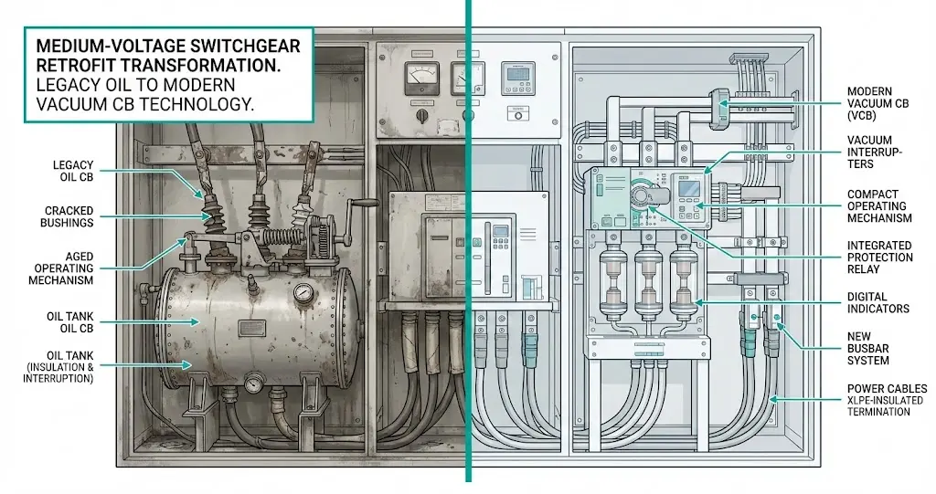
Circuit breaker retrofit means replacing the interrupter technology inside existing medium-voltage switchgear while keeping the original cubicle, busbars, and cable terminations intact. Instead of purchasing new switchgear lineups—involving civil work, extended outages, and substantial capital expenditure—retrofit allows engineers to upgrade only the circuit breaker itself. A well-executed retrofit delivers modern interrupting technology at 40–60% of full panel replacement cost.
This guide covers compatibility assessment, risk identification, and acceptance testing protocols for converting oil circuit breakers (OCBs) and SF₆ breakers to vacuum circuit breaker (VCB) technology across 3.6 kV to 40.5 kV applications.
Vacuum circuit breaker technology represents a fundamental departure from traditional switchgear in both arc-quenching mechanism and physical architecture.
In oil circuit breakers, the arc forms between separating contacts submerged in mineral oil. Intense heat (5,000–15,000 K at the arc core) decomposes the oil into hydrogen gas, creating a high-pressure bubble that cools and extinguishes the arc. This process requires 15–40 liters of oil per interrupter and generates combustible byproducts requiring regular maintenance.
SF₆ circuit breakers utilize sulfur hexafluoride gas at 400–600 kPa pressure, achieving arc extinction through electronegativity—SF₆ molecules capture free electrons, rapidly increasing dielectric strength. While effective, SF₆ carries a global warming potential 23,500 times greater than CO₂, driving regulatory pressure under EU F-gas regulations.
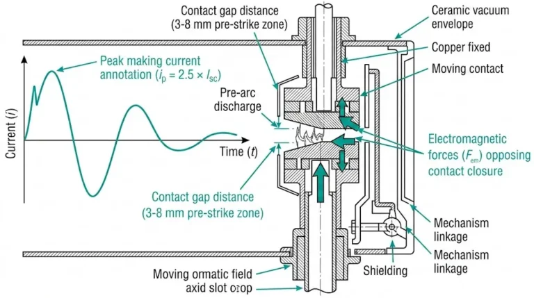
Vacuum interrupters operate differently. Arc extinction occurs in a sealed chamber maintained below 10⁻³ Pa, where metal vapor from CuCr contacts serves as the only conducting medium. Upon current zero crossing, this vapor condenses within 10–15 microseconds, restoring dielectric strength of 40–60 kV/mm across contact gaps of just 8–12 mm.
According to IEC 62271-100, vacuum circuit breakers rated for distribution applications must achieve fault interruption up to 40 kA symmetrical while maintaining contact erosion rates below 0.5 mg per ampere of interrupted current.

The compact vacuum interrupter design—typically 60% smaller than equivalent oil-filled units—creates both opportunities and challenges for retrofit compatibility.
[Expert Insight: Field Observations from Legacy Breaker Assessments]
Both technologies now face operational and regulatory pressures driving retrofit decisions.
Oil Circuit Breaker Challenges
Oil breakers require intensive maintenance—periodic oil filtering, dielectric testing, and contact inspection every 3–5 years. Fire hazards in enclosed spaces present significant safety concerns. Spare parts for 1970s–1990s vintage equipment have become increasingly scarce, with lead times extending to 6–12 months for critical components.
SF₆ Phase-Out Pressure
The European Union’s F-gas Regulation establishes progressive phase-down schedules for SF₆ applications. Leak detection costs, gas handling certification requirements, and end-of-life disposal expenses add 15–25% to total ownership costs compared to vacuum alternatives.
Vacuum Technology Advantages
VCBs achieve 10,000–30,000 mechanical operations versus 2,000–5,000 for oil types. No flammable or greenhouse gas media eliminates environmental compliance burdens. Maintenance intervals extend to 15–20 years under normal operating conditions.
For facilities evaluating their switching equipment options, exploring the complete vacuum circuit breaker product range provides specification details across voltage classes.
| Parameter | OCB | SF₆ Breaker | VCB |
|---|---|---|---|
| Maintenance interval | 3–5 years | 8–10 years | 15–20 years |
| Environmental concern | Oil disposal | GWP 23,500 | None |
| Fire risk | High | Low | Very low |
| Typical service life | 25–30 years | 25–30 years | 30+ years |
| Contact gap (12 kV) | 25–40 mm | 15–25 mm | 8–12 mm |
Successful retrofit requires precise alignment between new VCB assemblies and existing cubicle interfaces.
Breaker Truck Interface
Withdraw mechanism rail gauge varies by manufacturer: common values include 600 mm, 800 mm, and 1000 mm centers. Truck wheelbase and overall height clearance must permit smooth insertion and extraction. Primary disconnect finger clusters—vertical or horizontal configurations—must align with corresponding stationary contacts.
Pole Center Distance
Typical OCB pole centers measure 275 mm for 12 kV and 400 mm for 24 kV applications. VCB pole spacing may differ, requiring adapter plates to bridge dimensional gaps. Phase-to-phase clearances must maintain minimum 125 mm for 12 kV systems per IEC 62271-1.
Operating Mechanism Footprint
Spring-charged mechanisms differ dimensionally from motor-charged designs. Control cabinet relocation may prove necessary if housing geometry conflicts with cubicle depth. Interlock rod and lever geometry compatibility requires verification against original switchgear drawings.
Before ordering retrofit equipment, obtain original GA (General Arrangement) drawings and verify actual cubicle dimensions on-site. Corrosion or past modifications frequently cause 10–25 mm deviation from catalog values.

Electrical parameters require systematic verification before retrofit procurement.
Voltage Rating and BIL Matching
Confirm rated voltage (Ur) and lightning impulse withstand (Up) of the existing panel. Retrofit VCBs must meet or exceed original BIL specifications. A 12 kV panel with 75 kV BIL requires VCB rated ≥75 kV impulse withstand.
Short-Circuit Capacity
Verify prospective fault current (Isc) at the installation point. Retrofit VCB breaking capacity should include 20% growth margin for network expansion. Making capacity must achieve 2.5× or 2.6× symmetric fault current per applicable standards.
TRV Capability
Vacuum interrupters generally demonstrate favorable transient recovery voltage performance. However, transformer-fed and reactor-fed circuits may impose steep TRV conditions requiring verification of rate-of-rise capability (typically 1–2 kV/μs for distribution applications).
Creepage and Altitude Derating
Above 1000 m altitude, dielectric strength decreases approximately 1% per 100 m. Pollution class (I–IV) determines minimum creepage distance requirements. Retrofit VCB insulator creepage must match or exceed panel design basis.
Engineers seeking detailed specification guidance can reference VCB ratings and technical parameters for selection criteria.
| Parameter | Verify Against | Source Document |
|---|---|---|
| Rated voltage (Ur) | Panel nameplate | Original type test report |
| BIL / Up | Panel insulation class | GA drawings or IEC 62271-1 |
| Breaking capacity | Network fault study | Protection coordination study |
| Creepage distance | Pollution class | Site environmental assessment |
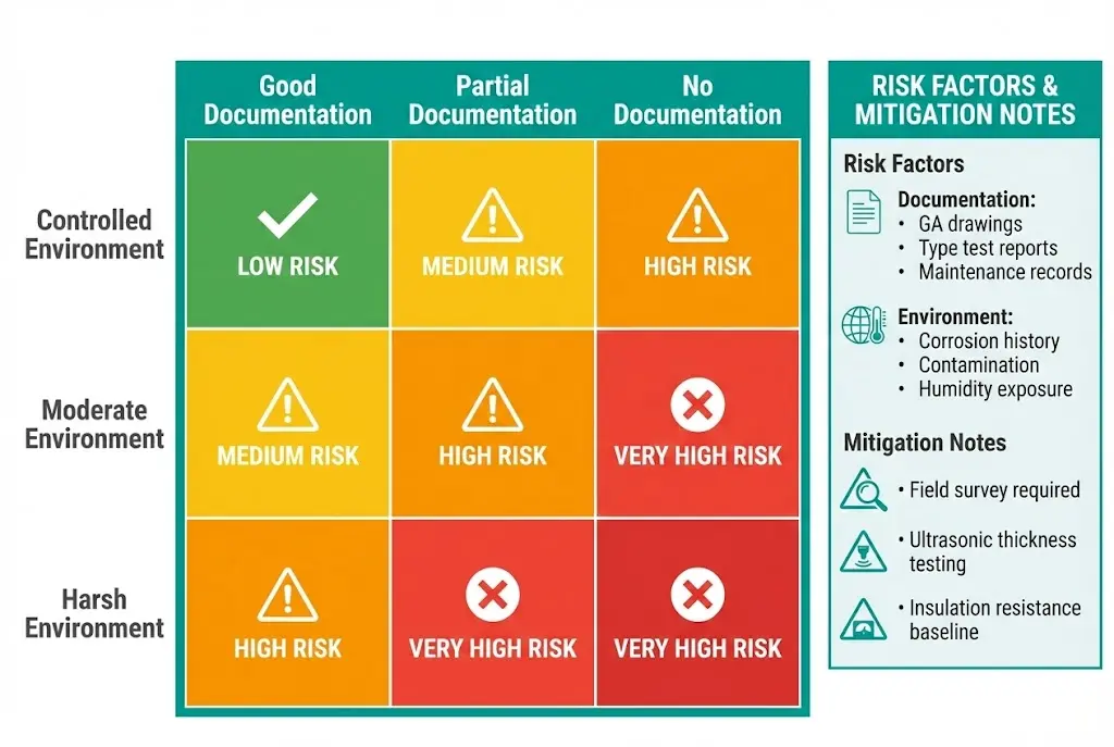
Risk identification before project commitment prevents costly mid-installation discoveries.
Risk 1: Hidden Panel Corrosion
Oil leaks degrade insulation materials, steel frames, and hinge mechanisms over decades. SF₆ moisture ingress indicates seal failures possibly affecting panel structural integrity. Mitigation requires thorough visual inspection combined with insulation resistance testing before retrofit commitment.
Risk 2: Incomplete Documentation
Missing GA drawings cause on-site dimension surprises. Specification discrepancies between documentation and actual installation delay commissioning. Field surveys with physical measurements and photographic documentation of all interfaces reduce this risk.
Risk 3: Current Chopping Overvoltage
Vacuum breakers may chop inductive current at higher levels than SF₆ technology, generating switching overvoltages on motors, reactors, and transformers. Installing surge arresters at load terminals mitigates this concern for highly inductive circuits.
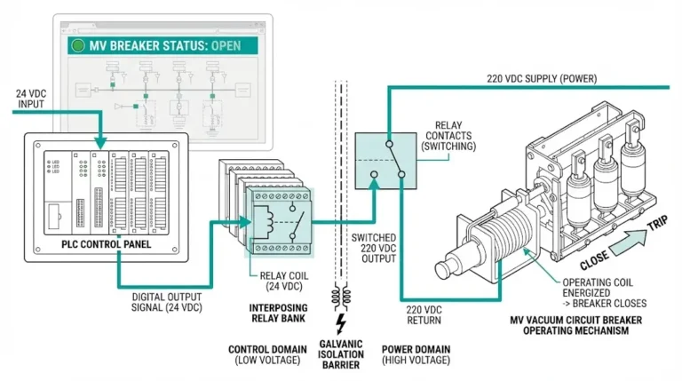
Risk 4: Control Circuit Timing Mismatch
VCB opening time of 25–50 ms operates faster than many legacy OCBs at 50–80 ms. Existing protection relay logic may assume slower breaker response. Review protection coordination studies and adjust relay settings if discrimination margins shrink.
Risk 5: Type Test Certification
Retrofit VCB installation in third-party panels may invalidate original type test certification. Obtain manufacturer retrofit compatibility statements. Consult local authorities if re-certification requirements apply.
Additional guidance on environmental factors affecting breaker selection appears in the indoor vs outdoor VCB selection guide.
| Risk Level | Scenario Description |
|---|---|
| Low | Same manufacturer, same era panel, complete documentation available |
| Medium | Different manufacturer, documentation available, controlled environment history |
| High | Unknown panel origin, no drawings, harsh environment or contamination history |
[Expert Insight: Lessons from 80+ Retrofit Projects]
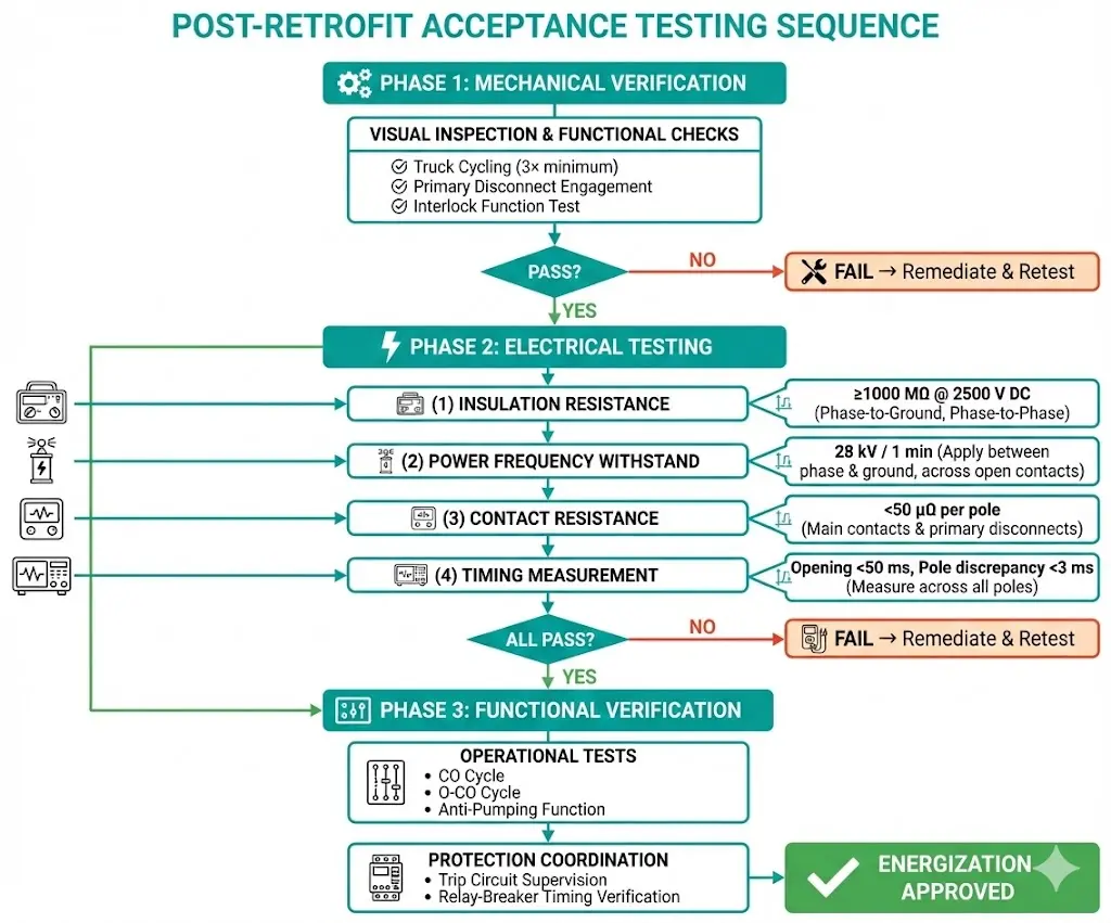
Systematic testing verifies retrofit success before energization.
Visual and Mechanical Inspection
Execute truck insertion and withdrawal for minimum three smooth cycles. Verify primary disconnect finger engagement depth against manufacturer specifications. Confirm secondary plug full insertion. Test interlock functions across all positions: test, service, isolated, and earthed.
Insulation Resistance Test
Measure phase-to-phase and phase-to-ground resistance with breaker open and closed. Acceptable values reach ≥1000 MΩ at 2500 V DC for 12 kV class equipment. Record ambient temperature and normalize readings to 20°C for comparison against factory baseline.
Power Frequency Withstand Test
Apply voltage per rated insulation level—28 kV for 1 minute on 12 kV equipment. Pass criteria require no flashover and no audible partial discharge indication.
Contact Resistance Measurement
Use micro-ohmmeter across each pole with breaker closed. Acceptable range falls below 50 μΩ for new VCB main contacts. Flag any deviation exceeding 20% from manufacturer datasheet values.
Timing and Travel Analysis
Measure opening time, closing time, and pole discrepancy (simultaneity). Contact travel curve analysis confirms proper mechanism operation. Opening time typically ranges 30–50 ms; pole discrepancy should remain below 3 ms.
Critical FAT verification points for retrofit VCBs include:
| Test | Method | Pass Criteria |
|---|---|---|
| Insulation resistance | 2500 V DC megger | ≥1000 MΩ (12 kV class) |
| Power frequency withstand | 28 kV / 1 min (12 kV class) | No flashover |
| Contact resistance | Micro-ohmmeter | <50 μΩ |
| Opening time | High-speed timer | Per datasheet ±10% |
| Pole discrepancy | Simultaneous measurement | <3 ms |
Structured project execution minimizes delays and ensures quality outcomes.
XBRELE supplies retrofit vacuum circuit breakers for 12 kV, 24 kV, and 40.5 kV applications with engineering support throughout the conversion process.
Engineering services include dimensional compatibility analysis from existing panel drawings, adapter plate and busbar interface design, control circuit wiring diagrams matched to legacy protection schemes, factory witness test coordination, and technical support during site commissioning.
Whether replacing aging oil circuit breakers or transitioning from SF₆ under environmental mandates, XBRELE retrofit VCBs deliver proven performance with flexible mounting configurations designed for compatibility with major switchgear platforms.
Contact XBRELE vacuum circuit breaker manufacturing to request a retrofit compatibility assessment. Submit your panel model and drawings—engineering response within 48 hours.
Q1: How long does a typical VCB retrofit project take from assessment to energization?
A straightforward single-breaker retrofit typically requires 6–10 weeks including feasibility study, equipment procurement, and commissioning; multi-panel projects with complex compatibility issues may extend to 14–20 weeks depending on adapter plate manufacturing lead times.
Q2: What percentage of cost savings can retrofit achieve compared to complete switchgear replacement?
Retrofit projects typically reduce capital expenditure by 40–60% compared to full panel replacement, though savings depend on cubicle condition, documentation availability, and whether adapter plates require custom engineering.
Q3: Can vacuum circuit breakers retrofit into any manufacturer’s legacy switchgear?
Retrofit feasibility varies by manufacturer and vintage—panels from major manufacturers with standardized dimensions adapt more readily, while proprietary designs from smaller suppliers may require extensive custom adapter engineering or prove impractical for retrofit.
Q4: What happens to residual oil contamination after removing an oil circuit breaker?
Residual hydrocarbon contamination exceeding 50 ppm on insulating surfaces can compromise vacuum interrupter performance; proper decontamination protocols include solvent cleaning, inspection under UV light, and insulation resistance verification before VCB installation.
Q5: Does retrofitting void the original switchgear warranty or type test certification?
Installing third-party retrofit equipment typically invalidates original type test certification; obtain written retrofit compatibility statements from the VCB manufacturer and consult local regulatory authorities regarding re-certification requirements for your jurisdiction.
Q6: How do protection relay settings change after VCB retrofit?
Vacuum circuit breakers operate 20–40% faster than most legacy oil breakers, potentially affecting protection coordination margins; review existing relay settings and verify discrimination times remain adequate, particularly for instantaneous overcurrent elements.
Q7: What maintenance schedule applies after converting from oil to vacuum technology?
Post-retrofit VCB maintenance typically shifts from 3–5 year intervals to 10–15 year major inspection cycles, with annual visual checks and contact resistance trending recommended to establish baseline performance data for condition-based maintenance programs.