Precisa das especificações completas?
Faça o download do nosso Catálogo de Produtos 2025 para obter desenhos detalhados e parâmetros técnicos de todos os componentes do quadro elétrico.
Obter catálogo
Faça o download do nosso Catálogo de Produtos 2025 para obter desenhos detalhados e parâmetros técnicos de todos os componentes do quadro elétrico.
Obter catálogo Faça o download do nosso Catálogo de Produtos 2025 para obter desenhos detalhados e parâmetros técnicos de todos os componentes do quadro elétrico.
Obter catálogo
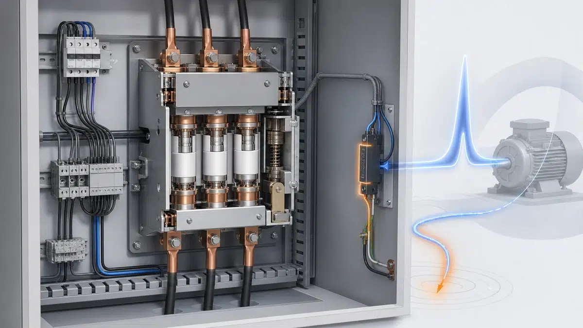
Os contatores a vácuo são essenciais no controle de motores de média tensão, em painéis de mineração e na manobra de bancos de capacitores. Sua confiabilidade ao longo de milhões de ciclos raramente recebe destaque: ela também depende de pequenos componentes de supressão, muitas vezes ignorados, ligados diretamente em paralelo às bobinas de comando. A **supressão de transientes da bobina do contator a vácuo** é a prática de engenharia que controla o pico transitório de tensão gerado sempre que a corrente da bobina é interrompida. Uma escolha incorreta pode danificar circuitos de acionamento, provocar desligamentos intempestivos, interferir em PLCs próximos e causar falha prematura do isolamento da bobina. A escolha correta pode fazer o contator durar mais que o equipamento que controla.
Este artigo explica por que ocorrem transientes na bobina, como eles diferem em circuitos de comando CC e CA, quais topologias de supressão são usadas e como selecionar e instalar o dispositivo correto para seu contator a vácuo. As orientações se baseiam na documentação dos fabricantes ABB e Schneider Electric.
—
Toda bobina de contator é um indutor. Quando a corrente passa por ela, energia é armazenada no campo magnético segundo a relação *E = ½LI²*. Quando uma chave de comando ou saída de estado sólido abre o circuito, essa energia precisa ser dissipada. Sem um caminho de supressão, a corrente percorre a impedância disponível — na prática, o espaço entre os contatos da chave que está abrindo ou o transistor de saída de uma placa de PLC. Em microssegundos, o pico de tensão resultante pode alcançar várias vezes a tensão nominal da alimentação.
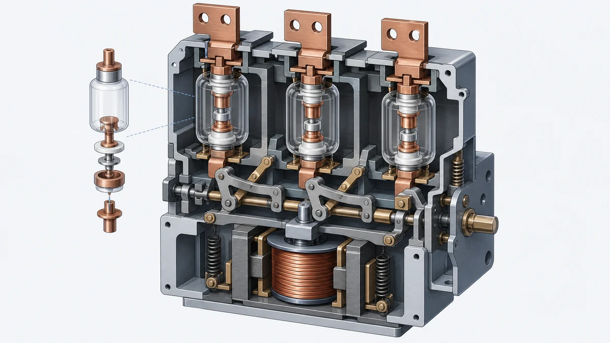
Em um contator a vácuo, o projeto do mecanismo agrava o problema. O manual ABB ConVac descreve um mecanismo eletromagnético e um módulo de alimentação de controle separado; em uma variante ConVac com retenção elétrica, o contator desarma assim que a alimentação auxiliar é removida. É justamente nesse instante que a energia armazenada na bobina fica sem caminho de dissipação, a menos que um supressor forneça uma via de descarga controlada. Quanto mais rápida a interrupção e maior a indutância da bobina, maior o pico. O Manual do contator a vácuo ABB ConVac é a fonte principal do requisito específico do produto mencionado aqui. Para comparar a aplicação com os formatos de equipamento disponíveis, consulte a linha de produtos de contatores XBRELE.
Consequências da ausência de supressão:
Entender a origem do problema torna a solução direta: fornecer um caminho de baixa impedância para a energia de descarga indutiva, sem envolver o contato da chave, a saída do acionador nem o isolamento da própria bobina.
—
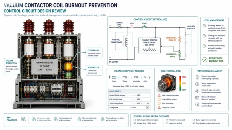
Circuitos de comando em corrente contínua são, de longe, os mais comuns em instalações modernas de contatores a vácuo, pois bobinas CC oferecem tempos de desarme rápidos e previsíveis e são compatíveis com saídas sink/source de PLC. A supressão CC se concentra no **diodo de roda livre**, também chamado de diodo de recirculação ou diodo de proteção.
**Como funciona o diodo de roda livre**
Um diodo retificador de silício padrão — normalmente um 1N4007 ou equivalente, especificado para 1 A e 1000 V PIV — é conectado em polaridade reversa aos terminais da bobina. Durante a energização normal, fica polarizado reversamente e não conduz corrente. Quando a chave de comando abre, o colapso do campo magnético inverte a polaridade da força contraeletromotriz da bobina. Essa polaridade inversa polariza diretamente o diodo, que conduz e faz circular a corrente armazenada na bobina até que a energia se dissipe como calor na resistência da bobina. O pico de tensão na chave é limitado a aproximadamente uma queda direta do diodo (0.7 V) acima do barramento de alimentação, em vez de centenas de volts sem limitação.
**Compensação: aumento do tempo de desarme**
Um diodo de roda livre simples suprime com muita eficácia o pico de tensão, mas tem um efeito colateral conhecido: atrasa o desarme do contator. Como a corrente da bobina decai lentamente pelo caminho de baixa impedância do diodo, em vez de cair rapidamente, o fluxo magnético no núcleo de ferro persiste por mais tempo e a armadura só é liberada quando o fluxo fica abaixo do limite de retenção. Em aplicações com tempo crítico — circuitos de parada de emergência, esquemas anti-reversão ou sequências em que um contator precisa abrir antes que outro feche — esse atraso pode ser inaceitável.
**Combinação de diodo e Zener (TVS)**
A solução de engenharia padrão para o atraso de desarme é colocar um diodo Zener ou supressor de transientes de tensão (TVS) em série com o diodo de roda livre, orientando o Zener contra a corrente de descarga. Assim, a corrente de recirculação precisa desenvolver uma tensão igual à tensão de ruptura do Zener antes de fluir. A corrente da bobina e o fluxo decaem mais rápido do que com um diodo simples, reduzindo o atraso, enquanto o pico transitório é limitado a um nível previsível igual a *V_supply + V_Zener + V_diode_forward*. Escolher um Zener com tensão de ruptura em torno do dobro da tensão de alimentação equilibra a supressão do pico e a velocidade do desarme.
**Uso de varistor (MOV) em CC**
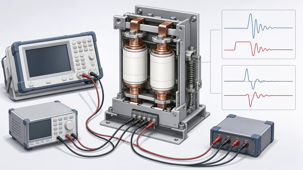
Um varistor de óxido metálico (MOV) conectado em paralelo à bobina CC limita os transientes quando a tensão excede a tensão varistor do MOV. Os dados do catálogo ABB identificam tanto um supressor a varistor quanto um supressor a diodo como acessórios para bobinas de contatores, com faixas compatíveis de tensão de comando — reforçando que o manual do dispositivo e os dados da bobina orientam a seleção. MOVs são menos precisos que combinações com Zener, mas robustos, bidirecionais e autoprotetores contra transientes ocasionais de alta energia. O guia de proteção da bobina contra transientes compara as opções de supressão para alimentação de comando CA e CC.
—
Bobinas de comando em corrente alternada apresentam um desafio de supressão fundamentalmente diferente. Como a tensão de alimentação inverte a polaridade a cada semiciclo, não se pode usar um diodo de roda livre simples: ele curto-circuitaria a alimentação durante o semiciclo negativo. A supressão CA precisa ser bidirecional.
**Por que os transientes CA ainda preocupam**
Embora a tensão senoidal de alimentação passe naturalmente por zero a cada 8.3 ms (60 Hz) ou 10 ms (50 Hz), momento em que a corrente da bobina poderia teoricamente comutar para zero com pouca energia armazenada, as chaves de comando reais nem sempre abrem nesse cruzamento. Uma chave que abra no pico ou perto dele ainda pode liberar energia armazenada significativa, especialmente em contatores com bobinas de alta indutância ou correntes operacionais elevadas.
Além disso, a própria alimentação CA está sujeita a transientes de manobra, surtos induzidos por raios e eventos de comutação de bancos de capacitores, capazes de acoplar vários quilovolts ao circuito de comando. Eles chegam aos terminais da bobina independentemente do impulso indutivo da própria bobina.
**Snubbers RC**
O supressor mais comum para bobinas CA é o snubber RC: um resistor e um capacitor em série conectados em paralelo à bobina. Quando o circuito abre, a corrente de descarga indutiva da bobina flui para o capacitor, que se carrega e limita a tensão de pico. O resistor limita a corrente de surto inicial no capacitor e amortece as oscilações. A Schneider documenta um módulo supressor RC de encaixe para uma faixa definida de circuitos de comando de 50–127 V AC, mostrando que a seleção para CA é específica à tensão e ao produto, e não uma escolha universal de diodo de roda livre CC. A interface mecânica de encaixe também permite instalação correta sem dependência de polaridade.
**Varistores para bobinas CA**
Varistores de óxido metálico são bidirecionais e, portanto, aplicáveis diretamente a circuitos CA. Um MOV selecionado com tensão varistor acima da tensão de pico CA (V_AC_rms × √2), mas abaixo da tensão de ruptura do isolamento da bobina, limita transientes positivos e negativos. A Schneider informa que um dispositivo de proteção contra surtos da bobina limita a tensão gerada quando ela abre e observa que a presença de supressão instalada de fábrica depende da configuração exata do contator e da bobina. Assim, o instalador deve confirmar essa condição na documentação do produto antes de adicionar dispositivos externos. Use o guia de falha térmica da bobina do contator para relacionar as opções de supressão aos riscos de tensão, aquecimento e ciclo de trabalho.
**Como evitar supressão redundante ou conflitante**
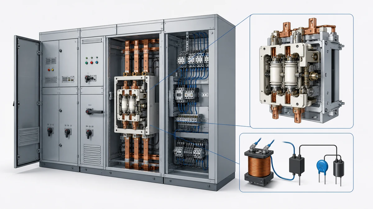
Adicionar um supressor externo a uma bobina que já possui varistor ou rede RC instalada de fábrica pode criar problemas. Dois MOVs em paralelo dividem a corrente de forma desigual durante transientes, e um deles pode sofrer sobrecarga. Um RC externo em paralelo com um RC de fábrica altera a constante de tempo efetiva e pode causar oscilação contínua. Sempre verifique a supressão de fábrica no manual ou diagrama de fiação específico do produto antes de especificar dispositivos adicionais.
—
O processo a seguir reúne as orientações dos fabricantes em um fluxo prático de seleção.
**Etapa 1 — Identifique o tipo e o valor nominal da tensão de comando**
Circuitos CC e CA exigem topologias diferentes. A tensão nominal determina as classes de tensão de todos os componentes. Os dados de catálogo da ABB informam faixas compatíveis de tensão de comando para seus supressores a varistor e a diodo; essas faixas devem corresponder à tensão nominal de comando da bobina, não à tensão do barramento do sistema.
**Etapa 2 — Consulte o manual específico do contator**
O manual ABB ConVac contém diagramas de fiação instalados e a descrição do módulo de alimentação de controle que orientam a configuração do circuito da bobina. Desviar da abordagem de supressão recomendada pelo fabricante pode invalidar a aprovação e causar comportamento temporal imprevisível no mecanismo eletromagnético.
**Etapa 3 — Determine se já há supressão de fábrica**
Como observa a Schneider, algumas combinações de contator e bobina já incluem um dispositivo de proteção contra surtos instalado. Inspecione os terminais e a carcaça da bobina e confira o número da peça na ficha técnica do produto.
**Etapa 4 — Escolha a topologia conforme os requisitos do tempo de desarme**
| Requisito | Topologia recomendada |
|---|---|
| Pico de tensão mínimo; tempo de desarme não crítico | Diodo de roda livre (somente CC) |
| Desarme rápido, circuito CC | Combinação em série de diodo + Zener |
| Circuito CA, faixa específica de tensão | Módulo snubber RC (conforme documentação Schneider) |
| Bidirecional, para CA e CC | MOV/varistor (conforme dados do catálogo ABB) |
| Surtos de energia muito alta (banco de capacitores, corrente de partida do transformador) | MOV mais RC em série |
**Etapa 5 — Verifique a instalação física**
Para módulos de encaixe, confirme que os trilhos de montagem ou blocos terminais da bobina correspondem à interface mecânica do supressor. Para componentes discretos ligados externamente, mantenha os condutores o mais curtos possível — condutores longos acrescentam indutância parasita e reduzem a eficácia da limitação. Em circuitos CC, confira a polaridade do diodo com um medidor antes de energizar.
—
Mesmo um supressor selecionado corretamente pode falhar se for instalado ou mantido de forma inadequada.
**Posicionamento da fiação**
Instale o supressor o mais próximo possível dos terminais da bobina. Qualquer condutor entre o contato da chave ou a saída do acionador e o supressor permanece desprotegido do pico transitório durante o breve tempo de propagação anterior à condução do supressor. Se um PLC acionar um contator a vácuo remoto, instale o supressor nos terminais da bobina, não na placa de saída do PLC. Coordene os caminhos de feedback e comando com o guia de controle por PLC e relé de interface antes do comissionamento.
**Inspeção periódica**
MOVs se degradam com a absorção acumulada de energia. Cada evento transitório envelhece parcialmente o material do varistor; após eventos suficientes, a tensão de limitação aumenta e o dispositivo acaba falhando em circuito aberto. Em aplicações de alta frequência de ciclos (várias operações por hora), inspecione os MOVs anualmente ou conforme o cronograma de manutenção do fabricante. Um MOV degradado apresenta descoloração, trincas ou tensão de limitação diferente do valor nominal quando testado com um testador de varistores.
**Verificação do estado dos diodos**
Diodos de roda livre podem falhar em curto-circuito, criando um curto CC sobre a alimentação da bobina — uma falha latente que impede sua energização. Uma simples medição de resistência no circuito, com o contator desenergizado e a alimentação isolada, pode detectar esse modo de falha.
**Documentação e identificação**
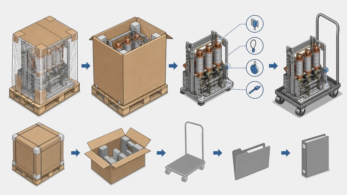
Após instalar componentes de supressão, atualize o diagrama de fiação conforme construído. Identifique o supressor com o número da peça e a data de instalação. Em circuitos críticos para a segurança, registre a instalação no histórico de manutenção para que os técnicos futuros entendam por que o componente está presente e não o removam durante uma inspeção de rotina.
—
A supressão da bobina de um contator a vácuo consiste em conectar diretamente em paralelo à bobina um componente limitador de tensão — como diodo, MOV ou rede RC — para absorver a energia liberada pelo colapso do campo magnético quando o circuito de comando abre. Sem supressão, a bobina gera um transiente de alta tensão capaz de danificar contatos, destruir transistores de saída de PLC e criar interferência eletromagnética. A Schneider Electric documenta que um dispositivo de proteção limita a tensão gerada quando a bobina do contator abre, confirmando essa função protetora. Em contatores a vácuo, o mecanismo eletromagnético rápido e a possibilidade de desarme com retenção elétrica tornam a supressão eficaz particularmente importante.
A supressão de retorno indutivo em CC usa um componente unidirecional — normalmente um diodo de roda livre ou uma combinação de diodo e Zener — que fornece um caminho de circulação para a corrente de descarga indutiva quando a alimentação CC é interrompida. Isso funciona porque a polaridade da força contraeletromotriz da bobina é previsível em um circuito CC. A supressão de bobina CA não pode usar um diodo simples porque a tensão de alimentação inverte a polaridade a cada semiciclo. Circuitos CA exigem dispositivos bidirecionais, como snubbers RC ou varistores de óxido metálico. O módulo RC de encaixe da Schneider, projetado para uma faixa específica de circuito de comando de 50–127 V AC, demonstra que a seleção para CA é específica à tensão e ao produto, não uma solução universal de diodo de roda livre CC.
Um diodo de roda livre é um diodo retificador conectado em polaridade reversa em paralelo a uma bobina CC. Durante a energização normal, ele fica polarizado reversamente e não afeta o circuito. Quando o acionador abre o circuito de comando, a força contraeletromotriz da bobina se inverte e polariza diretamente o diodo. Ele então conduz, fazendo circular a energia indutiva armazenada, que se dissipa como calor na resistência da bobina. A tensão na saída do acionador é limitada a aproximadamente uma queda direta do diodo acima do barramento de alimentação — geralmente menos de 1 V — em vez das centenas de volts de um pico indutivo sem proteção. Essa proteção é essencial para placas de saída a transistor de PLC que acionam bobinas de contatores a vácuo, pois a tensão máxima da saída normalmente fica apenas um pouco acima da tensão de alimentação.
Um módulo supressor RC combina em série um resistor e um capacitor e é fornecido como acessório de encaixe ou montagem em terminal para bobinas de contatores em circuitos de comando CA. Quando o circuito CA abre, a corrente de descarga indutiva flui para o capacitor, carregando-o e limitando o pico de tensão, enquanto o resistor amortece oscilações. A Schneider Electric documenta um módulo RC específico para uma faixa de circuito de comando de 50–127 V AC, demonstrando que a seleção precisa corresponder à faixa exata de tensão e à família do produto. Supressores RC são preferíveis quando o circuito da bobina pode sofrer tanto impulso indutivo quanto surtos vindos da alimentação e quando a montagem física por encaixe proporciona instalação segura e independente da polaridade.
Um diodo de roda livre conectado em paralelo à bobina CC desacelera a queda do fluxo magnético porque fornece um caminho de baixa resistência para a corrente de descarga circular, em vez de colapsar abruptamente. Isso atrasa a liberação da armadura e, em alguns projetos, aumenta o tempo de desarme de poucos milissegundos para dezenas de milissegundos. Em aplicações de parada de emergência ou anti-reversão, o atraso pode ser inaceitável. A combinação de diodo e Zener resolve isso ao forçar a corrente de descarga a passar por uma tensão reversa definida, acelerando o colapso do fluxo. MOVs e snubbers RC afetam menos o tempo de desarme que diodos de roda livre simples. O manual ABB ConVac descreve o mecanismo eletromagnético e deixa claro que o comportamento temporal é um parâmetro crítico de projeto; portanto, cada componente de supressão deve ser avaliado diante da especificação publicada de tempo de desarme do contator.