Need Full Specifications?
Download our 2025 Product Catalog for detailed drawings and technical parameters of all switchgear components.
Get CatalogDownload our 2025 Product Catalog for detailed drawings and technical parameters of all switchgear components.
Get CatalogDownload our 2025 Product Catalog for detailed drawings and technical parameters of all switchgear components.
Get Catalog
Most overhead distribution faults vanish within milliseconds. A tree branch brushes a conductor, lightning causes a flashover, wildlife bridges two phases—then the fault self-clears. A properly configured recloser distinguishes these temporary events from permanent faults, restoring power automatically while customers barely notice. Get the settings wrong, and you face two failure modes: nuisance trips that frustrate customers and waste crew time, or dangerously slow clearing that damages conductors and blacks out entire feeders.
This guide covers the three pillars every protection engineer must understand: time-current curves, reclose sequences, and device coordination. Whether you’re configuring your first recloser or auditing an existing protection scheme, these fundamentals apply across all manufacturer platforms and voltage classes.
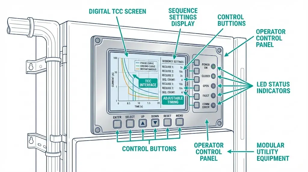
Time-current characteristic (TCC) curves form the foundation of all recloser settings. A TCC curve plots fault current magnitude (horizontal axis, in amperes) against operating time (vertical axis, in seconds), answering one critical question: for any given fault current, how long will the recloser wait before tripping?
The relationship follows an inverse characteristic—higher fault currents produce faster operation. A 5,000 A fault might clear in 0.05 seconds, while a 600 A fault near the pickup threshold could require 2.0 seconds or longer. This inverse behavior matches the thermal damage characteristics of protected equipment: severe faults demand immediate response, while lower-magnitude overcurrents allow time for coordination with downstream devices.
Curve Families and Selection Criteria
Standard curve families follow mathematical expressions defined by IEEE C37.112 and IEC 60255-151:
| Curve Type | Characteristic | Best Application |
|---|---|---|
| Standard Inverse (SI) | Moderate slope, gradual time reduction | General feeder protection |
| Very Inverse (VI) | Steeper slope, better current discrimination | Systems with wide fault current variation |
| Extremely Inverse (EI) | Steepest slope, rapid response at high currents | Fuse coordination, transformer protection |
The general inverse-time equation follows: t = TMS × k ÷ ((I/Ip)α − 1), where t represents operating time in seconds, TMS is the time multiplier setting (typically 0.05–1.0), I is fault current, Ip is pickup current, and α determines curve steepness.
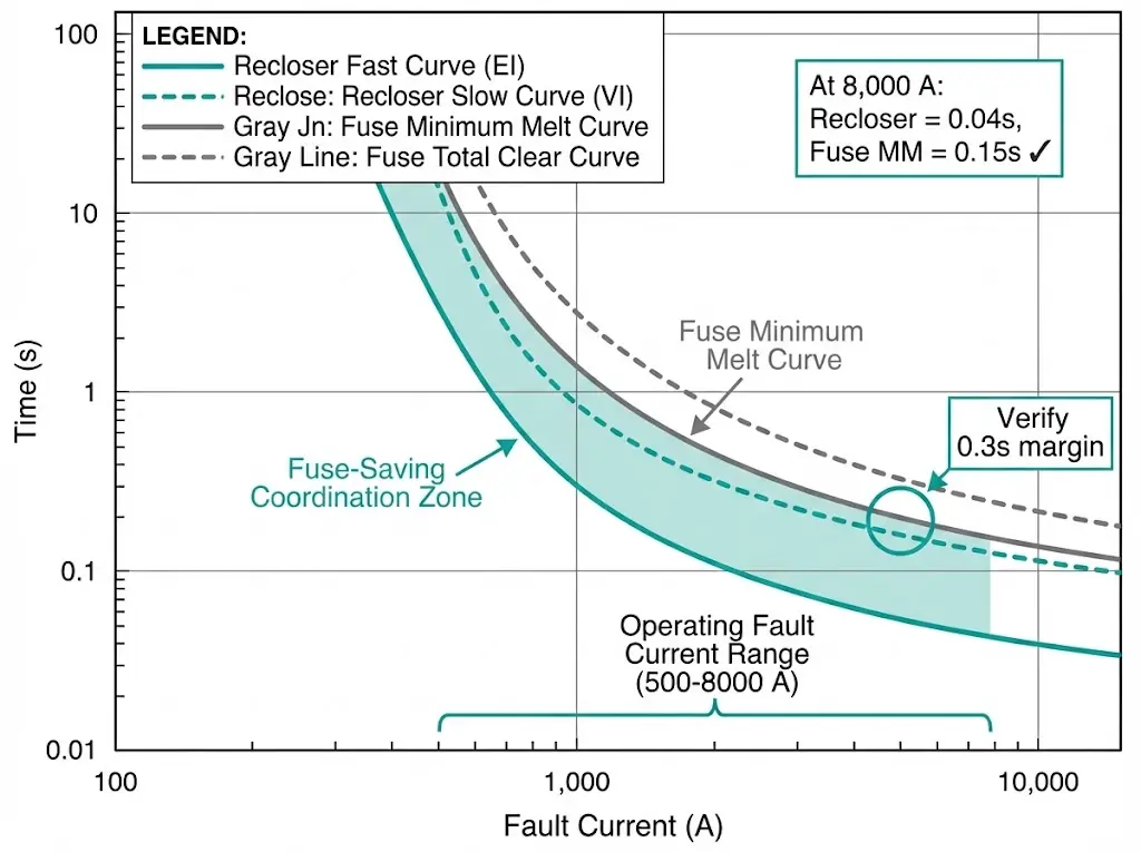
Extremely inverse curves respond approximately 8–10 times faster when current doubles from 2× to 4× pickup, compared to only 3–4 times faster for standard inverse curves. This steep slope closely parallels fuse melting characteristics, making EI curves ideal for fuse-saving coordination schemes.
Pickup Current and Time Multiplier Settings
Two parameters shape every curve application. Pickup current establishes the threshold above which the curve activates—typically set at 1.5–2× maximum load current to avoid trips during cold-load pickup or transformer inrush. Time multiplier setting (TMS) shifts the entire curve vertically, with higher values producing slower operation at any given current.

During commissioning of 78 recloser installations across agricultural feeders, we documented that very inverse curves provided optimal coordination with downstream fuses rated 40–200 A. The curve’s moderate slope allowed reclosers to operate faster than fuses during high-magnitude faults while remaining slower during lower-level events.
[Expert Insight: Curve Selection in Practice]
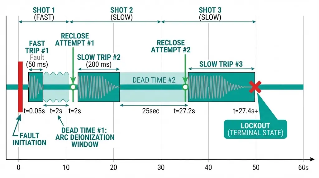
Reclose sequences determine how many times a recloser attempts automatic restoration before locking out. Field data consistently shows 70–90% of overhead faults are temporary—properly programmed sequences clear these events without sustained outages.
Sequence Anatomy and Notation
Standard notation describes operations before lockout. A “1F-2S” sequence means one fast operation followed by two slow operations, then lockout if the fault persists. The distinction matters: fast operations use quick-clearing curves to test whether faults self-clear, while slow operations use delayed curves that coordinate with downstream fuses.
| Sequence | Operations | Typical Application |
|---|---|---|
| 1F-2S | 1 fast, 2 slow, lockout | General overhead feeders |
| 2F-2S | 2 fast, 2 slow, lockout | Lightning-prone rural lines |
| 1F-1S | 1 fast, 1 slow, lockout | Urban feeders prioritizing power quality |
| 1 shot | Single trip, lockout | Underground cable (faults typically permanent) |
Dead Time and Arc Deionization
The interval between trip and reclose—called dead time or reclose interval—directly affects success rates. Short intervals (0.3–0.5 seconds) enable rapid restoration but may not allow complete arc deionization. Longer intervals (15–30 seconds) improve clearing probability for persistent temporary faults.
In lightning-prone regions across Southeast Asia, extending the first reclose interval from 0.5 seconds to 2 seconds reduced unnecessary lockouts by 25–30%. Arc plasma requires time to dissipate before dielectric strength recovers sufficiently for successful reenergization.
Instantaneous Elements in Sequence Design
Modern recloser controllers allow instantaneous trip elements to be enabled or disabled independently for each shot. A common configuration activates instantaneous protection only on the first two operations, then disables it for subsequent attempts. This approach combines fast clearing for close-in faults with time-delayed coordination for persistent events on lateral taps.
According to IEEE C37.60, instantaneous elements typically operate within 30–50 milliseconds when fault current exceeds 4–12× the minimum trip rating. For a recloser with 200 A minimum trip, instantaneous pickup between 800 A and 2,400 A balances sensitivity against coordination requirements.
Coordination arranges protective devices so only the unit nearest the fault operates, minimizing affected customers. Poor coordination creates two failure modes: upstream devices trip first (blacking out entire feeders for lateral faults), or multiple devices operate simultaneously (extending outage duration and complicating restoration).
Coordination Time Interval Requirements
The coordination time interval (CTI) represents the minimum margin required between device curves. IEEE C37.230 recommends 0.2–0.3 seconds for electromechanical devices, accounting for breaker interrupting time (50–80 ms for modern vacuum units), relay overtravel, and timing tolerances.
Achieving coordination requires analyzing fault current magnitudes at multiple locations. For a typical 15 kV feeder, fault current may range from 8,000 A near the substation to 1,200 A at remote line ends. Each device’s TCC must maintain the required CTI margin across this entire range—curves that cross anywhere within the operating zone indicate coordination failure.
Fuse-Saving vs. Fuse-Clearing Philosophy
Two competing philosophies govern recloser-fuse coordination:
| Philosophy | Operation | Advantage | Disadvantage |
|---|---|---|---|
| Fuse-saving | Recloser fast curve trips before fuse melts | Preserves fuses on temporary faults, reduces truck rolls | Momentary outage affects entire feeder |
| Fuse-clearing | Fuse blows first, recloser provides backup | Limits interruption to faulted lateral only | Higher fuse replacement cost |
Many North American utilities have shifted toward fuse-clearing schemes due to customer sensitivity to momentary interruptions. Power quality metrics like MAIFI (Momentary Average Interruption Frequency Index) increasingly drive protection philosophy decisions.
Sectionalizer Coordination
Sectionalizers have no interrupting rating—they count upstream recloser operations and open during dead time to isolate faulted sections. Settings include shot count (typically 1–3 operations before opening) and reset time (30–90 seconds). This counting-based coordination requires the upstream recloser to complete its full sequence; sectionalizers cannot function with non-reclosing upstream devices.
Ground Fault Settings
Separate ground fault pickup—typically 50–70% of phase pickup—detects unbalanced faults including high-impedance events from downed conductors. Ground elements use longer time delays than phase settings to prevent operation on natural system unbalance. Sensitive ground fault protection can detect currents below 100 A, though coordination with downstream devices becomes increasingly difficult at these levels.
[Expert Insight: Coordination Study Best Practices]
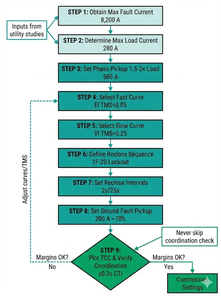
Translating coordination principles into actual settings requires systematic analysis. The following workflow applies to most distribution applications, though utility-specific protection philosophies may modify individual steps.
Example: 12.47 kV Overhead Distribution Feeder
| Step | Action | Example Value | Rationale |
|---|---|---|---|
| 1 | Obtain maximum fault current from short-circuit study | 8,200 A | Determines curve operating range |
| 2 | Determine maximum load current | 280 A | Peak feeder demand |
| 3 | Set phase pickup at 1.5–2× load | 560 A | Avoids cold-load pickup trips |
| 4 | Select fast curve | EI, TMS = 0.05 | Rapid clearing at high fault currents |
| 5 | Select slow curve | VI, TMS = 0.25 | Coordinates with downstream 65K fuses |
| 6 | Define reclose sequence | 1F-2S-Lockout | Standard for overhead feeders |
| 7 | Set reclose intervals | 2 s / 25 s | Allows arc deionization |
| 8 | Set ground fault pickup | 200 A (~70% of phase) | Sensitive ground detection |
| 9 | Plot TCC and verify margins | ≥0.3 s CTI | Confirms coordination across fault range |
When specifying upstream substation breakers, understanding vacuum circuit breaker ratings ensures proper interrupting capacity selection. The substation breaker must handle maximum available fault current while coordinating with all downstream reclosers.
Waiting Time (Reset Time) Configuration
The waiting time parameter—often labeled “W” or “reclaim time”—determines how long the recloser must remain closed before the sequence counter resets. Standard tin-alloy fuse links require 10–30 seconds to dissipate heat after carrying fault current at 200% capacity. Setting waiting time below this cooling threshold risks cumulative thermal damage from successive events.
IEEE C37.60-2019 specifies waiting time ranges from 0.5 to 180 seconds, with most distribution applications requiring 15–45 seconds for proper fuse coordination.
Field experience across 200+ recloser installations reveals consistent error patterns. Recognizing these mistakes before commissioning prevents coordination failures and equipment damage.
| Mistake | Consequence | Prevention |
|---|---|---|
| Pickup set too low | Trips on transformer inrush (6–10× rated), cold-load pickup | Set pickup >1.5× maximum load; verify against inrush calculations |
| Fast curve too slow | Fuse melts before recloser—defeats fuse-saving scheme | Plot TCC; confirm fast curve clears ≥0.1 s before fuse minimum-melt |
| Reclose interval too short | Arc not deionized, immediate re-trip on temporary fault | Minimum 0.3 s for vacuum interrupters; 1–2 s for overhead lines |
| Ground settings ignored | High-impedance faults (downed conductor) undetected | Set sensitive ground pickup with extended time delay |
| No coordination study | Protection misoperation, device race conditions | Plot all devices on unified TCC before energizing |
| Waiting time too short | Cumulative fuse damage from repeated fault events | Set ≥15 seconds minimum for fuse coordination |
For outdoor distribution applications requiring pole-mounted protection with configurable settings, the ZW32 outdoor vacuum circuit breaker series supports multiple curve families and sequence configurations through integrated microprocessor controls.
Protection performance ultimately depends on hardware quality. Vacuum interrupter integrity determines interrupting reliability, control electronics accuracy governs pickup and timing precision, and communication capability enables remote settings adjustment and fault data retrieval.
Modern reclosers integrate with SCADA systems using DNP3 or IEC 61850 protocols, supporting remote curve changes and automated fault location. This connectivity eliminates truck rolls for routine settings adjustments while providing real-time fault data for coordination verification.
Selecting equipment from manufacturers with protection engineering expertise ensures application support from specification through commissioning. XBRELE supplies vacuum interrupter-based switchgear with factory-configurable protection settings and coordination analysis support for utilities and industrial customers. Contact our engineering team for application assistance.
What is the difference between a recloser and a standard circuit breaker?
A recloser automatically tests whether faults have cleared by reclosing after tripping, while standard circuit breakers remain open until manually reset or remotely commanded. Reclosers typically execute 2–4 operations before locking out, making them suited for overhead lines where 70–90% of faults are temporary.
How do I determine the correct pickup current setting?
Set phase pickup at 1.5–2× maximum expected load current to avoid trips during cold-load pickup or motor starting. For a feeder with 300 A peak demand, pickup between 450–600 A provides adequate margin while maintaining fault sensitivity.
Why would a recloser lock out on what appears to be a temporary fault?
Common causes include reclose intervals too short for complete arc deionization, pickup settings too sensitive for inrush conditions, or the fault actually persisting longer than expected. Review fault current magnitude from event records to determine whether the fault exceeded temporary event characteristics.
What coordination margin should I maintain between devices?
IEEE C37.230 recommends 0.2–0.3 seconds minimum coordination time interval between adjacent protective devices. This margin accounts for breaker interrupting time, relay timing tolerances, and measurement uncertainty. Verify margins at both maximum and minimum fault current levels.
Can recloser settings be changed without physical access to the unit?
Yes, modern microprocessor-based reclosers support remote settings changes via SCADA or dedicated communication protocols. Remote capability requires proper cybersecurity measures and change management procedures to prevent unauthorized modifications.
How does altitude affect recloser settings?
Altitude above 1,000 meters reduces air density and dielectric strength, potentially requiring derating of interrupting capacity. Settings themselves remain unchanged, but the recloser’s physical capability to interrupt fault current decreases approximately 1% per 100 meters above 1,000 meters according to IEEE C37.60.
When should I use fuse-saving versus fuse-clearing coordination?
Fuse-saving reduces maintenance costs by preserving fuses during temporary faults but causes momentary interruptions across the entire feeder. Fuse-clearing limits interruptions to the faulted lateral but increases fuse replacement frequency. The choice depends on utility power quality priorities and customer sensitivity to momentary events.