Need Full Specifications?
Download our 2025 Product Catalog for detailed drawings and technical parameters of all switchgear components.
Get CatalogDownload our 2025 Product Catalog for detailed drawings and technical parameters of all switchgear components.
Get CatalogDownload our 2025 Product Catalog for detailed drawings and technical parameters of all switchgear components.
Get Catalog
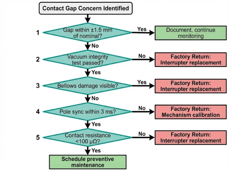
A medium-voltage vacuum circuit breaker must open or close its contacts within 30–80 milliseconds—whether the command arrives during a winter night or peak summer load. Stored-energy mechanisms make this possible by decoupling energy accumulation from energy release. Springs compress over several seconds, store elastic potential energy (typically 150–400 joules for 12 kV class breakers), and remain held by precision latches until a control signal triggers release.
When these mechanisms fail, protection schemes become unreliable. In field assessments across 200+ industrial substations, we’ve documented that mechanical linkage issues—corroded latches, fatigued springs, and misaligned tripping links—account for approximately 70% of all stored-energy mechanism malfunctions. This article examines the dominant failure patterns, their root causes, and diagnostic approaches that help maintenance engineers identify problems before protection gaps develop.
Stored-energy mechanisms in vacuum circuit breakers rely on precise mechanical linkages to transfer spring force through latches, tripping links, and contact assemblies. Contact welding and pivot point binding represent two distinct failure mechanisms that produce similar symptoms—the breaker refuses to operate on command.
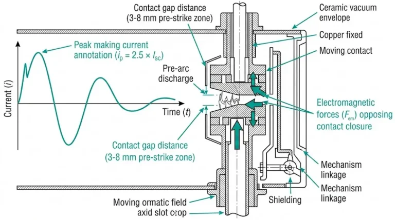
Contact welding occurs when fault currents generate sufficient heat at the main contacts to fuse metal surfaces together. During interruption of currents exceeding 25 kA, contact temperatures can reach 1,100–1,400°C at the interface—well above the melting point of copper-tungsten contact materials. The stored-energy spring may develop adequate opening force (typically 800–1,200 N for 12 kV breakers), yet the mechanism stalls because welded contacts exceed available separation force.
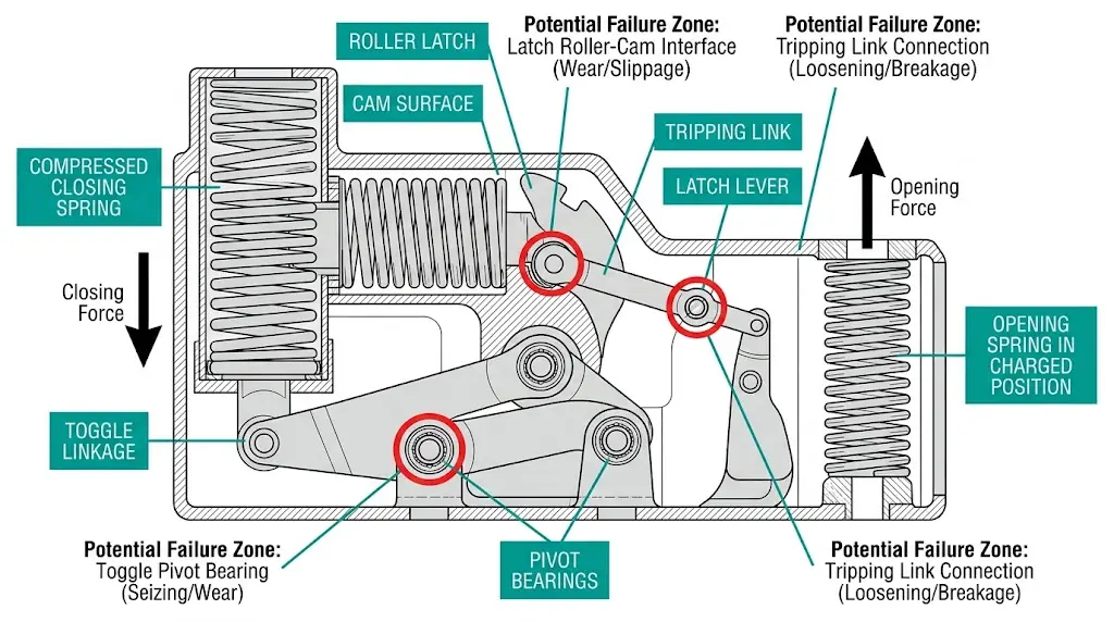
Binding points develop through different mechanisms entirely. Pivot pins, toggle linkages, and latch engagement surfaces accumulate contamination, corrosion products, and lubricant degradation over operational cycles. Real-world installations frequently experience binding failures at 3,000–5,000 cycles when maintenance intervals are extended beyond manufacturer recommendations.
Three critical binding locations require inspection:
Field observations from mining and petrochemical applications demonstrate that ambient contamination accelerates binding failures significantly. Breakers in clean environments maintain proper linkage function for 8–10 years, while contaminated environments may require intervention within 18–24 months.
Common mechanical failure patterns in stored-energy systems typically originate from two primary sources: corroded latch surfaces and degraded spring assemblies. Maintenance assessments indicate approximately 40% of mechanism failures trace back to these root causes.
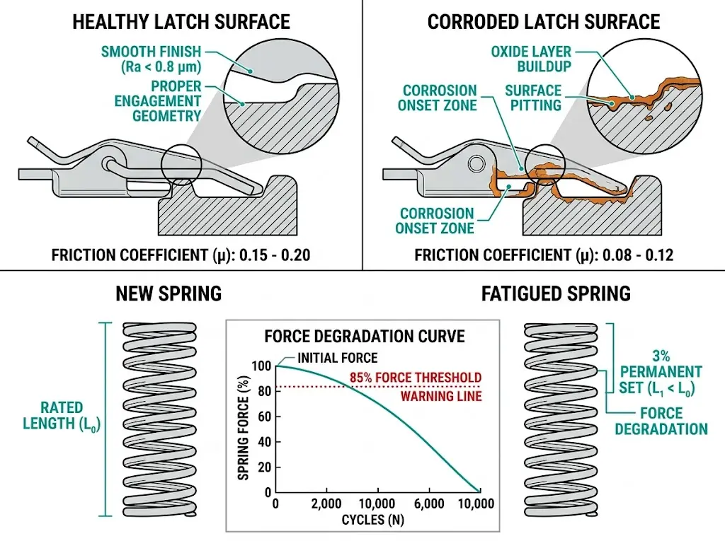
Latch engagement surfaces require precise contact geometry to maintain holding force during the charged state. When corrosion develops on hardened steel latch faces, effective contact area decreases, reducing the friction coefficient from typical values of 0.15–0.20 down to 0.08–0.12. This degradation allows premature release under vibration or thermal cycling.
Environmental factors accelerate latch corrosion significantly. Installations in coastal or high-humidity environments (relative humidity >80%) experience corrosion onset 3–5 times faster than climate-controlled indoor applications. The oxide layer creates surface irregularities that increase trigger force requirements by 15–25%, potentially exceeding the trip coil’s rated output.
Closing springs and charging springs must maintain specific force characteristics throughout their operational life. According to IEC 62271-100, these springs shall retain at least 90% of rated force after 10,000 mechanical operations (Class M2). Field testing reveals that springs operating near their upper temperature limit (typically 40°C ambient) experience accelerated stress relaxation.
Spring force degradation follows predictable patterns: initial force loss of 2–4% occurs within the first 1,000 operations, followed by gradual decline of 0.1–0.2% per 1,000 cycles thereafter. When spring force drops below the 85% threshold, contact closing velocity decreases from the specified 1.5–2.0 m/s to potentially hazardous levels below 1.2 m/s, risking contact welding during fault interruption.
[Expert Insight: Latch Inspection Priorities]
- Measure latch engagement depth at each maintenance interval—values below 2.5 mm warrant immediate attention
- Check for visible oxide buildup on roller and cam surfaces using 10× magnification
- Verify trip coil current draw; increases exceeding 20% from baseline indicate rising mechanical resistance
- Document surface finish condition—degradation below Ra 0.8 μm signals replacement requirements
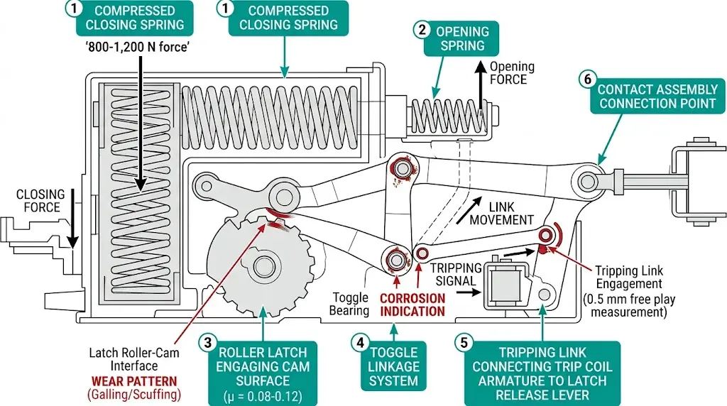
The latch mechanism serves as the critical interface between stored spring energy and the contact drive system. During charging, closing springs compress and lock against a precisely machined latch surface. The latch must withstand static holding forces of 2,000–5,000 N while maintaining a release threshold responsive to trip coil currents as low as 1.5 A.
Latch geometry degradation is the primary failure initiator. The latch roller and catch surface operate under Hertzian contact stress, typically reaching 800–1,200 MPa at the engagement point. Surface hardness specifications per IEEE C37.04 require VCB mechanism components to maintain 58–62 HRC to resist this contact stress over 10,000 mechanical operations.
Three distinct latch failure modes dominate troubleshooting scenarios:
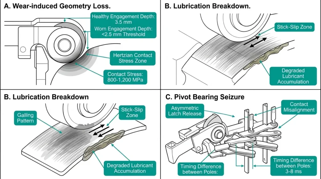
Wear-induced geometry loss manifests as progressively shorter latch engagement depth. When engagement decreases below manufacturer-specified minimums, spring force vectors shift unfavorably, causing nuisance trips under vibration or thermal expansion.
Lubrication breakdown accelerates surface galling between the latch roller and pivot pin. Operating environments above 45°C or below −25°C challenge standard lithium-based greases, causing stick-slip behavior that increases release force variability by 15–30%.
Pivot bearing seizure creates asymmetric latch release, where one side releases 3–8 ms before the other. This generates contact misalignment and uneven arc distribution across interrupter poles.
Preventive maintenance protocols should verify latch engagement depth, pivot pin freedom, and lubrication condition at intervals not exceeding 5 years or 2,000 operations—whichever occurs first.
Spring fatigue, latch surface degradation, and tripping link wear follow characteristic failure trajectories that maintenance engineers can identify before catastrophic malfunction occurs.
Closing and opening springs typically deliver initial charging forces of 800–1,200 N, depending on breaker rating. Over operational cycles, spring steel experiences stress relaxation that reduces stored energy by approximately 2–5% per 10,000 operations. This degradation accelerates in environments where ambient temperatures exceed 40°C.
Critical wear indicators include permanent set (δpermanent > 3% of original length) and surface pitting from corrosion ingress. Springs operating in humid mining environments show 15–20% faster degradation rates compared to climate-controlled switchgear rooms. IEC 62271-100 mandates that operating mechanisms maintain rated closing velocity (typically 0.8–1.2 m/s) throughout their mechanical endurance rating of 10,000 operations.
Tripping link pivot points accumulate wear debris that increases friction torque by 10–25% over service life, directly affecting trip time consistency. For indoor versus outdoor installations, environmental exposure differences create distinct wear acceleration patterns—outdoor mechanisms face moisture ingress, UV degradation of seals, and wider temperature cycling that accelerates pivot wear.
According to reliability data published by CIGRE, mechanical component failures represent the dominant failure category in medium-voltage switchgear, with trip chain components accounting for the largest single subset.
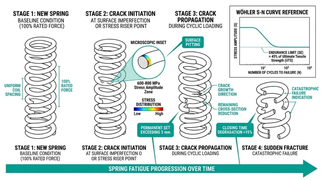
Fatigue-induced spring fracture represents one of the most consequential failure patterns affecting circuit breaker reliability. Spring fatigue failures account for approximately 23% of all stored-energy mechanism malfunctions based on field data from industrial installations.
Closing springs operate under cyclic loading conditions, with each operation producing stress reversals that progressively weaken spring material. The fatigue mechanism follows the Wöhler curve principle—spring wire endures repeated stress cycles until microscopic crack initiation occurs at stress concentration points.
Critical fatigue parameters include: spring wire stress amplitude (typically 600–800 MPa for chrome-silicon steel), endurance limit (approximately 45% of ultimate tensile strength for most spring steels), and accumulated cycle count. Springs rated for 10,000 mechanical operations must maintain consistent force output within ±5% throughout their service life according to IEC 62271-100 requirements for operating mechanism endurance.
Experienced maintenance technicians recognize several indicators before catastrophic spring fracture occurs. Closing time degradation exceeding 15% from commissioning values often correlates with spring fatigue progression. Visual inspection may reveal surface cracks, corrosion pitting acting as stress risers, or permanent set reducing free length by more than 3 mm from original specifications.
Spring replacement intervals should follow both calendar-based (typically 8–10 years) and operation-based (5,000–7,500 cycles for closing springs) criteria—whichever occurs first.
[Expert Insight: Spring Health Assessment]
- Record closing time at each maintenance interval and trend against commissioning baseline
- Inspect spring surfaces under adequate lighting for crack initiation at coil ends (highest stress concentration)
- Measure free length and compare to nameplate—permanent set exceeding 3% indicates replacement
- In high-humidity environments, schedule spring inspection at 50% of normal intervals
Spring charging system failures account for approximately 35% of all circuit breaker mechanical malfunctions. The charging motor must overcome both spring resistance and mechanical friction throughout the charging stroke—motor current draw during charging provides a valuable diagnostic indicator.
Healthy systems draw 3–5 A at 110 V DC control voltage. Degraded mechanisms often show current spikes exceeding 7 A due to increased friction or partial spring binding.
Spring force degradation follows predictable patterns governed by Hooke’s Law: F = k × x, where spring constant k decreases over service life. When k drops below 90% of rated value, closing velocity falls below the 1.5–2.0 m/s threshold required for proper contact engagement per IEC 62271-100 operating requirements.
Spring charging mechanisms incorporate multiple pivot points, cams, and roller followers that experience concentrated wear. Cam follower bearings represent common failure locations, particularly in breakers operating in environments with ambient temperatures exceeding 40°C or humidity above 80% RH.
Lubrication breakdown accelerates wear exponentially. Manufacturer-specified lubricants maintain viscosity within 100–150 cSt at operating temperatures, but degraded lubricants can reach 300+ cSt, dramatically increasing charging motor load and mechanism stress.
Regular assessment parameters for degradation trending:
| Parameter | Healthy Range | Warning Threshold |
|---|---|---|
| Charging time | 8–15 seconds | >18 seconds |
| Motor current (110 V DC) | 3–5 A | >7 A |
| Spring force retention | >90% of rated | <85% of rated |
| Closing velocity | 1.5–2.0 m/s | <1.2 m/s |
Mechanical reliability starts with quality manufacturing and extends through proper maintenance support. At XBRELE, we engineer stored-energy mechanisms with hardened latch components, corrosion-resistant spring materials, and factory-adjusted linkages verified through IEC 62271-100 mechanical endurance testing.
Whether you need replacement mechanism components for existing switchgear or complete vacuum circuit breakers with proven mechanical endurance, our engineering team provides technical support from specification through commissioning.
Contact XBRELE to discuss mechanism specifications, request performance documentation, or inquire about replacement parts for your stored-energy operating mechanisms.
Q: How often should stored-energy mechanism springs be inspected?
A: Spring inspection intervals depend on operating frequency and environment—typically every 2–3 years for normal indoor service, shortened to 12–18 months for high-humidity, contaminated, or high-cycle applications.
Q: What causes a circuit breaker to fail to trip when commanded?
A: Common causes include latch binding from lubrication breakdown, tripping link misalignment creating insufficient release force, trip coil failure, or contact welding from previous fault interruptions that exceeded the mechanism’s separation force capacity.
Q: How can maintenance engineers detect spring fatigue before fracture occurs?
A: Monitor closing time trends against commissioning baselines—degradation exceeding 15% indicates spring weakening. Visual inspection under magnification can reveal surface cracks at coil ends where stress concentration is highest.
Q: What environmental conditions accelerate stored-energy mechanism failures?
A: High humidity (>80% RH), ambient temperatures exceeding 40°C, airborne contamination (dust, chemical vapors), and salt-laden coastal atmospheres all accelerate corrosion, lubrication breakdown, and surface degradation in mechanism components.
Q: Why does trip time vary between operations on the same breaker?
A: Trip time variation typically indicates developing mechanical problems—worn pivot bearings creating inconsistent friction, latch surface irregularities from corrosion, or tripping link play exceeding design tolerances. Variation greater than ±5 ms from baseline warrants investigation.
Q: Can individual mechanism components be replaced, or must the entire mechanism be changed?
A: Individual components (latches, springs, pivot pins, tripping links) can often be replaced if manufacturer-approved parts are available and remaining component geometry remains within specification. Complete mechanism replacement becomes necessary when multiple components show degradation or frame distortion has occurred.
Q: What is the typical service life of a stored-energy operating mechanism?
A: Well-maintained mechanisms in favorable environments achieve 15–25 years of service life or 10,000 mechanical operations (Class M2 per IEC 62271-100). Actual lifespan depends heavily on operating frequency, environmental severity, and maintenance quality.