Need Full Specifications?
Download our 2025 Product Catalog for detailed drawings and technical parameters of all switchgear components.
Get CatalogDownload our 2025 Product Catalog for detailed drawings and technical parameters of all switchgear components.
Get CatalogDownload our 2025 Product Catalog for detailed drawings and technical parameters of all switchgear components.
Get Catalog

Medium-voltage switchgear fails for many reasons—mechanical wear, electrical overloads, manufacturing defects. But environmental stress inside enclosures accounts for a disproportionate number of insulation failures that proper monitoring could prevent. Temperature and humidity sensors form the first line of defense, detecting conditions that lead to condensation, surface tracking, and accelerated equipment aging before these problems cause unplanned outages.
In field deployments across 200+ substation installations throughout industrial and utility applications, we’ve documented that environmental parameter deviations directly correlate with accelerated insulation degradation and contact erosion in vacuum circuit breakers. The enclosure microclimate differs dramatically from ambient readings—a switchgear room might register 25°C and 60% RH on a wall-mounted sensor while busbar compartments inside run 15–20°C hotter during load periods.
Consider where switchgear actually operates. Coastal substations face salt-laden humidity year-round. Industrial plants expose enclosures to process heat, steam, and chemical vapors. Tropical installations endure 90%+ relative humidity for months. Even temperate-climate indoor switchgear rooms experience daily thermal cycling that drives moisture in and out of enclosures.
The fundamental mechanism driving monitoring requirements stems from the interaction between ambient conditions and SF6 gas behavior. SF6 maintains its superior dielectric strength of approximately 89 kV/cm at atmospheric pressure only when moisture content remains below 150 ppmv. Temperature fluctuations beyond the operational range of -25°C to +40°C cause pressure variations within sealed compartments, potentially triggering false low-pressure alarms or genuine seal degradation.
What happens when moisture accumulates unchecked:
Environmental monitoring transforms maintenance strategy from reactive to predictive. Sensors tracking temperature and humidity trends reveal developing problems weeks or months before failure—enough time to schedule intervention during planned outages.
Condensation occurs when surface temperature drops to or below the dew point of surrounding air. This distinction matters: air temperature alone doesn’t determine condensation risk. A metal enclosure panel at 18°C will collect moisture from 25°C air at 70% RH because that air’s dew point sits at approximately 19°C.
Field conditions frequently expose sensors to relative humidity levels from 5% RH in arid climates to 95% RH in tropical or coastal installations. The critical concern is dew point proximity—when enclosure temperatures approach the dew point (Tambient ≤ Tdew + 3°C), condensation risk increases dramatically, potentially causing surface tracking and insulation degradation in SF6 compartments.
The degradation pathway follows a predictable sequence. Moisture film forms on insulator surfaces. Contaminants dissolve into this film, creating weak electrolyte solutions. Under voltage stress, leakage currents flow across the surface. Localized heating from these currents causes dry bands. Voltage concentrates across dry bands, initiating partial discharge. Repeated discharge activity erodes insulation material until flashover occurs.
SF6 compartments face an additional risk. During arc interruption, SF6 decomposes into reactive byproducts including sulfur fluorides. When moisture is present, these compounds form hydrofluoric and sulfuric acids that corrode metal components and degrade elastomer seals. Maintaining moisture content below 150 ppmv prevents this reaction chain.

According to IEC 62271-1, environmental monitoring systems must detect conditions that could compromise the minimum functional pressure of SF6, typically 0.1–0.15 MPa gauge for medium-voltage applications. Humidity sensors positioned within switchgear compartments track dew point temperatures, which must remain at least 10°C below the minimum expected operating temperature to prevent condensation on critical insulation surfaces.
[Expert Insight: Condensation Prevention]
- Maintain enclosure surfaces 3–5°C above calculated dew point at all times
- Cable entry zones and enclosure bases are highest-risk condensation areas
- Morning hours present peak condensation risk due to overnight temperature drop
- SF6 compartments require tighter moisture limits (150 ppmv) than general enclosure humidity targets
The sensor integration architecture typically employs RTD (Resistance Temperature Detector) elements with ±0.3°C accuracy paired with capacitive polymer humidity sensors achieving ±2% RH precision across the 10–95% relative humidity range. Selecting the right temperature sensor depends on the measurement point, required accuracy, and environmental conditions.
RTD (Pt100) sensors use platinum wire resistance change with temperature. They deliver high accuracy (±0.1–0.3°C) and excellent long-term stability, making them ideal for busbar hot-spot monitoring and critical junction points. Response time runs 1–5 seconds—adequate for thermal mass monitoring but not for rapid transient detection. Higher cost limits deployment to critical measurement points.
NTC Thermistors offer faster response (0.1–1 second) at significantly lower cost. The semiconductor element’s resistance decreases with temperature, producing non-linear output that requires linearization circuitry. Accuracy typically falls in the ±0.5–1.0°C range. Best application: enclosure ambient monitoring and anti-condensation heater feedback control.
Thermocouples handle extreme temperature ranges but suffer from EMI susceptibility in switchgear environments. Transient voltages exceeding 1 kV/μs during fault interruption can induce measurement errors. Use only when temperature ranges exceed RTD or thermistor capabilities.

| Parameter | RTD (Pt100) | NTC Thermistor | Thermocouple (Type K) |
|---|---|---|---|
| Accuracy | ±0.1–0.3°C | ±0.5–1.0°C | ±1.5–2.5°C |
| Response Time | 1–5 s | 0.1–1 s | 0.5–2 s |
| Temperature Range | −200 to +600°C | −40 to +150°C | −200 to +1200°C |
| EMI Immunity | High | Moderate | Low |
| Relative Cost | High | Low | Moderate |
| Switchgear Application | Busbar monitoring | Ambient/heater control | Rarely used |
Testing across mining applications with frequent load switching showed that sensors positioned away from direct thermal radiation sources maintained 15% better long-term calibration stability compared to poorly positioned units.
Relative humidity sensing and dew point measurement serve different purposes. RH sensors indicate moisture content relative to saturation at current temperature. Dew point transmitters indicate the temperature at which condensation will occur. For condensation prevention, dew point is more directly actionable.
Capacitive humidity sensors dominate switchgear monitoring installations. A thin polymer film changes dielectric constant as it absorbs moisture, shifting capacitance proportionally to RH. Cost remains low, size is compact, and accuracy of ±2–3% RH suits most applications. The limitation: calibration drift over time requires periodic verification, typically every 12–24 months.
Dew point transmitters calculate or directly measure the condensation threshold temperature. Chilled mirror instruments cool a reflective surface until condensation forms, detecting the precise dew point. More commonly, transmitters calculate dew point from simultaneous RH and temperature measurements. Direct condensation risk indication makes these instruments valuable for critical substations and coastal installations despite 3–5× higher cost than basic RH sensors.
SF6 moisture analyzers measure moisture content in parts per million by volume (ppmv), the relevant unit for gas-phase moisture. [VERIFY STANDARD: IEC 60480 specifies moisture limits for SF6 gas in service]. These specialized instruments typically integrate with SF6 density monitoring systems on gas-insulated switchgear components.
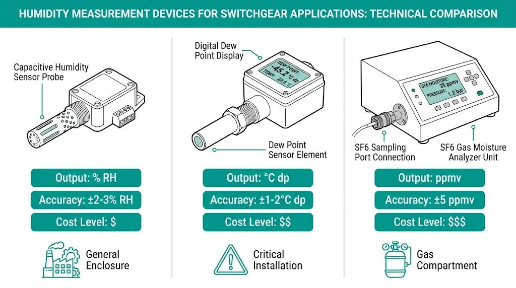
| Sensor Type | Output | Accuracy | Drift Concern | Cost | Best Application |
|---|---|---|---|---|---|
| Capacitive RH | % RH | ±2–3% | Moderate | Low | General enclosure monitoring |
| Dew Point Transmitter | °C dp | ±1–2°C | Low | High | Critical installations, coastal sites |
| SF6 Moisture Analyzer | ppmv | ±5 ppmv | Low | Very High | SF6 gas compartments |
Sensor placement determines measurement relevance. A perfectly accurate sensor in the wrong location provides misleading data.
Temperature sensor locations:
Humidity sensor placement:
In coastal substations, sensors placed at enclosure tops consistently read 10–15% RH lower than bottom-mounted sensors during morning hours—missing critical condensation windows entirely.
SF6 compartment sensors require dedicated gas-phase access, typically through a monitoring port on the SF6 tank. Integration with gas density relays simplifies installation when available.

[Expert Insight: Sensor Installation Pitfalls]
- Avoid mounting humidity sensors directly above heater elements—convective airflow creates false dry readings
- Route sensor cables away from power conductors to minimize EMI pickup
- Use shielded cables with proper grounding for all analog sensor signals
- Install redundant sensors at critical measurement points where single-sensor failure creates blind spots
Effective monitoring requires actionable alarm setpoints—thresholds that trigger response before damage occurs without generating nuisance alarms that operators learn to ignore.
Recommended setpoints for medium-voltage switchgear based on field experience and standards guidance:
| Parameter | Warning | Alarm | Trip/Lockout | Notes |
|---|---|---|---|---|
| Enclosure Temperature | >45°C | >55°C | >65°C | Adjust for rated ambient |
| Busbar Temperature Rise | >50K above ambient | >65K | >80K | [VERIFY STANDARD: IEC 62271-1 temperature rise limits] |
| Relative Humidity | >70% RH | >80% RH | >90% RH | Activate heater at 65% |
| Dew Point Margin | <8°C above surface | <5°C | <3°C | Primary condensation indicator |
| SF6 Moisture Content | >150 ppmv | >250 ppmv | >500 ppmv | Per IEC 60480 guidance |
SCADA integration enables remote monitoring and historical trending. Common signal protocols include:
Data logging at 15-minute intervals captures gradual environmental trends. During alarm conditions, increase logging to 1-minute intervals to capture event progression. Trend analysis over weeks or months reveals seasonal patterns and identifies compartments with developing seal or ventilation problems—enabling predictive maintenance scheduling before conditions reach alarm thresholds.
Proper VCB selection accounts for expected environmental conditions from initial specification, reducing monitoring burden in well-matched installations.
Sensors detect problems. Active systems prevent them.
Heater sizing follows a general rule: 50–100W per cubic meter of enclosure volume, adjusted for climate severity. Tropical and coastal installations trend toward the higher end; temperate indoor environments need less. Undersized heaters run continuously without maintaining adequate temperature differential above dew point. Oversized heaters waste energy and can overheat enclosures during warm weather.
Control strategy matters as much as sizing. Thermostat-only control activates heaters when temperature drops, but temperature alone doesn’t indicate condensation risk. Combined thermostat-humidistat control activates heaters when humidity rises above setpoint (typically 65% RH) AND temperature is below threshold. This approach prevents unnecessary heating during dry cold conditions.
Ventilation versus sealing presents a fundamental design choice:
Field data from Southeast Asian utility installations showed sealed enclosures without heaters experienced 300% higher insulation failure rates compared to properly heated installations of the same switchgear ratings.
XBRELE supplies complete medium-voltage switchgear solutions designed for demanding environmental conditions—from vacuum circuit breakers rated for extreme temperatures to SF6 switchgear with integrated monitoring provisions.
Our switchgear component portfolio includes:
Request a consultation to discuss environmental monitoring requirements for your switchgear installation. Our engineering team provides application-specific recommendations based on site conditions, equipment ratings, and operational requirements.
Q: What relative humidity level triggers condensation risk in switchgear enclosures?
A: Condensation risk depends on the relationship between humidity and temperature rather than humidity alone—when enclosure surface temperature falls within 3–5°C of the dew point, condensation becomes likely regardless of whether relative humidity reads 60% or 80%.
Q: How often should switchgear humidity sensors be recalibrated?
A: Capacitive humidity sensors typically maintain acceptable accuracy for 12–24 months between calibrations, while dew point transmitters hold calibration longer but benefit from annual verification against a reference standard.
Q: Can standard humidity sensors measure SF6 gas moisture content?
A: No—standard RH sensors measure water vapor in air, while SF6 compartments require specialized moisture analyzers calibrated to measure parts per million by volume in the gas phase, typically using aluminum oxide or chilled mirror sensing elements.
Q: What causes anti-condensation heaters to fail prematurely?
A: Most heater failures result from undersizing (continuous operation at maximum output), poor mounting that restricts convective airflow, or thermostat failures that allow overheating—sizing heaters with 20–30% margin above calculated requirements extends service life significantly.
Q: Do outdoor VCB installations need different monitoring than indoor switchgear?
A: Outdoor installations face wider temperature swings, direct solar radiation, and rain ingress pathways that require more robust sensor specifications (wider operating range, higher IP rating) and tighter alarm thresholds compared to climate-controlled indoor switchgear rooms.
Q: How quickly should environmental monitoring systems respond to changing conditions?
A: Temperature sensors with 1–5 second response times adequately track thermal mass changes in switchgear compartments, while humidity sensors should respond within 30 seconds to capture rapid moisture ingress events such as those occurring during enclosure door opening or seal failures.
Q: What is the minimum dew point margin recommended for SF6 switchgear?
A: Industry practice maintains internal surfaces at least 10°C above the lowest expected dew point temperature, providing margin for measurement uncertainty and localized cold spots that may exist at thermal bridges in the enclosure structure.