Need Full Specifications?
Download our 2025 Product Catalog for detailed drawings and technical parameters of all switchgear components.
Get CatalogDownload our 2025 Product Catalog for detailed drawings and technical parameters of all switchgear components.
Get CatalogDownload our 2025 Product Catalog for detailed drawings and technical parameters of all switchgear components.
Get Catalog
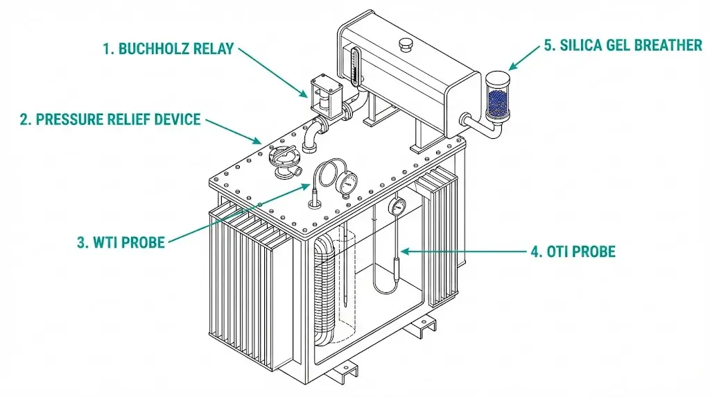
Oil-immersed transformers face constant internal threats that remain invisible from outside: gas evolution from insulation breakdown, thermal stress on windings, pressure buildup during faults, and moisture infiltration through breathing cycles. Protective accessories—Buchholz relay, pressure relief device, temperature indicators, and silica gel breather—serve as the transformer’s sensory system, detecting abnormalities before catastrophic failure occurs.
From a procurement standpoint, these accessories represent less than 5% of total transformer cost yet determine whether a developing fault becomes a scheduled maintenance event or a complete asset loss. In our experience commissioning over 200 oil-immersed transformers across industrial substations, properly specified accessories have consistently provided early warning of internal problems—often detecting issues days or weeks before other protection systems respond.
When evaluating power distribution transformers, treat each accessory as a discrete specification item requiring verification rather than an interchangeable add-on. The following sections examine each device from a buyer’s perspective, covering operating principles, specification parameters, and quality indicators that distinguish reliable equipment from commodity products.
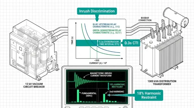
A Buchholz relay is a gas-actuated protective device installed in the pipe connecting a transformer’s main tank to its conservator. It detects incipient faults through gas accumulation and oil surge analysis—two distinct physical phenomena that indicate different fault severities.
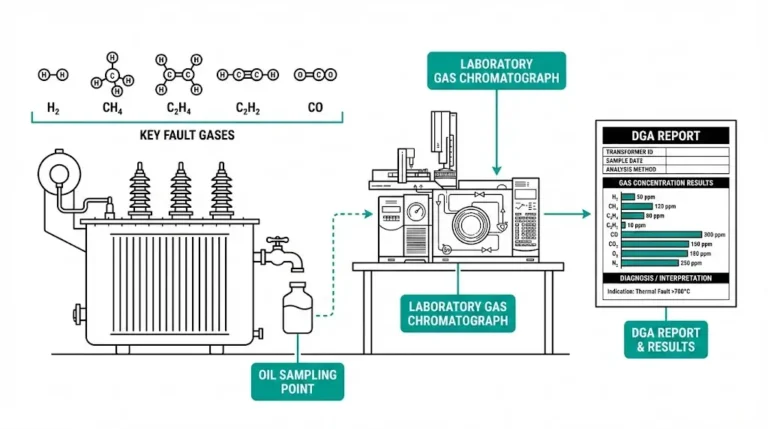
The operating principle relies on fundamental chemistry: internal faults decompose transformer oil and cellulose insulation into gases. At temperatures above 300°C, oil breaks down into hydrogen, methane, acetylene, and other hydrocarbons. Minor faults such as partial discharge or local overheating produce gas at rates of 50–100 cm³/hour. Severe arcing faults generate explosive gas volumes that displace oil at velocities exceeding 0.7 m/s.
Two-Stage Protection Mechanism
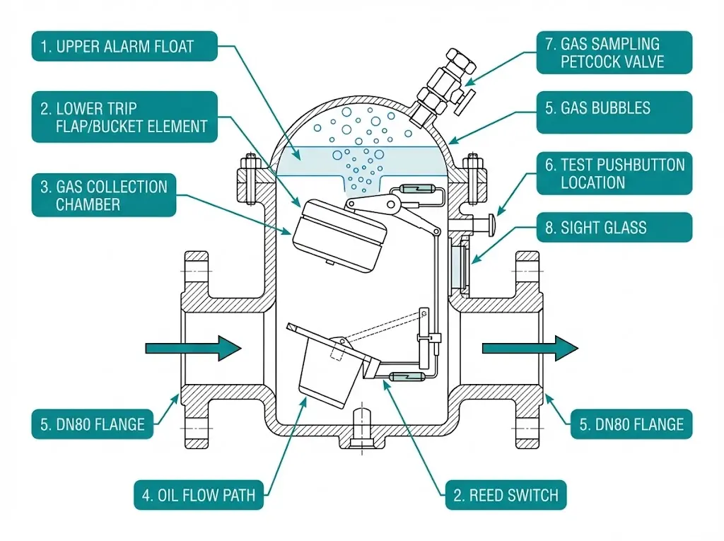
The relay housing contains two float elements serving distinct functions:
The upper float responds to gradual gas accumulation. As fault gases collect in the relay chamber and oil level drops, the float tilts to activate an alarm contact. This stage typically triggers when accumulated gas reaches 100–250 cm³—providing hours or days of advance warning before serious damage develops.
The lower element—a hinged flap or bucket—detects rapid oil displacement from major faults. When internal arcing creates sudden gas generation, the resulting oil surge deflects this element within 50–100 milliseconds, initiating immediate circuit breaker trip signals.
Specification Checklist for Buyers
| Parameter | Typical Values | Verification Point |
|---|---|---|
| Pipe connection | DN50 / DN80 / DN100 | Must match conservator pipe diameter |
| Alarm contact rating | 250V AC, 0.5A | Verify relay panel input compatibility |
| Trip contact rating | 250V AC, 1.0A | Confirm breaker trip circuit requirements |
| Oil flow trip velocity | 0.7–1.2 m/s | Appropriate for transformer MVA rating |
| Gas collection volume | 200–300 cm³ | Sufficient for dissolved gas analysis sampling |
| Test pushbutton | Included | Essential for commissioning verification |
Field observations across mining and petrochemical installations reveal that the alarm function detects approximately 70% of incipient faults before catastrophic failure. The trip function provides backup protection for high-energy events producing immediate gas generation.
[Expert Insight: Buchholz Relay Installation]
- Mounting pipe must maintain 1.5–3% gradient slope toward conservator for proper gas migration
- Gas sampling petcock enables dissolved gas analysis without relay removal
- False trips commonly result from air entrapped during oil filling or improper mounting angle
- Mercury switches in older relays require level verification; modern reed switches are position-tolerant
When catastrophic faults generate rapid gas evolution inside a transformer tank, pressure rises dangerously within milliseconds. The pressure relief device (PRD) provides mechanical protection independent of electrical systems—venting gases before tank rupture occurs.
PRD vs. Sudden Pressure Relay
Two distinct devices address overpressure conditions:
The PRD valve uses a spring-loaded diaphragm that opens at preset pressure—typically 50–70 kPa above atmospheric. When activated, it physically releases oil and gas to atmosphere, then reseats automatically (self-resealing type) or remains open (frangible disc type). Response time is under 50 milliseconds.
The sudden pressure relay (SPR) is an electrical device detecting rate-of-pressure-rise rather than absolute pressure. It sends trip signals to circuit breakers but does not physically relieve pressure. Many specifications require both: SPR for fast electrical trip, PRD for mechanical venting.
Mounting and Sizing Considerations
PRDs mount on the tank top cover or upper sidewall, with the discharge port oriented away from personnel walkways. Size correlates with transformer MVA rating and oil volume—larger units require greater venting capacity to prevent pressure buildup exceeding structural limits.
Verify factory drilling matches the PRD flange pattern before shipment. Retrofit installations often require custom adapter plates when replacing PRDs from different manufacturers.
Buyer Quality Indicators
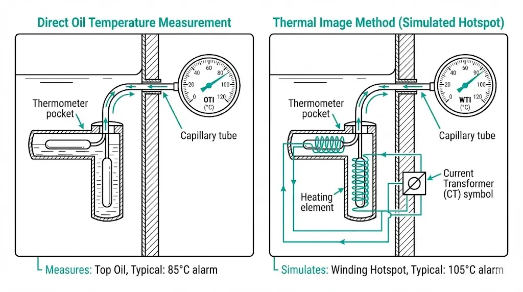
Transformer windings operate significantly hotter than surrounding oil. The oil temperature indicator (OTI) measures top-oil temperature directly, while the winding temperature indicator (WTI) estimates the hottest-spot winding temperature using a thermal simulation method. Both measurements are essential—relying on OTI alone underestimates actual insulation stress by 15–30°C under load.
Why Both Indicators Matter
OTI provides straightforward measurement via a thermometer pocket in the tank wall, reading the temperature of oil near the top of the tank. This value reflects cooling system performance and ambient conditions but does not indicate actual winding thermal stress.
WTI addresses this gap through the thermal image principle. A current transformer supplies reduced current to a heating resistor mounted inside the WTI thermometer pocket. This heater adds temperature rise proportional to I²R losses in the winding, causing the WTI reading to approximate hottest-spot temperature without requiring a sensor embedded in the coil itself.
Thermal Image Calibration
Accurate WTI readings require proper calibration during transformer design:
Factory documentation should specify these parameters. Field recalibration is possible but requires detailed knowledge of transformer thermal design.
Setting Alarm and Trip Thresholds
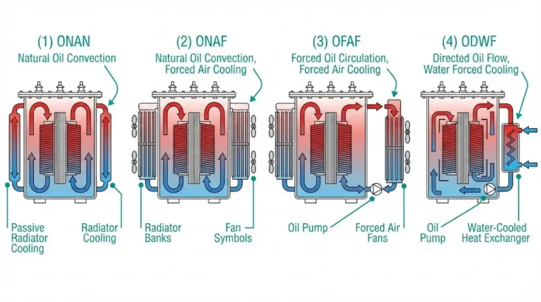
Temperature setpoints depend on insulation class and cooling method. For standard Class A insulation (105°C thermal limit) in ONAN-cooled oil-immersed transformer units:
| Indicator | Alarm Setting | Trip Setting | Monitoring Target |
|---|---|---|---|
| OTI | 85°C | 95°C | Top-oil temperature |
| WTI | 105°C | 120°C | Simulated hottest-spot |
These values align with thermal loading guidance in IEEE C57.91. Actual factory settings may differ based on specific transformer design—verify documentation before energization.
[Expert Insight: Temperature Indicator Maintenance]
- Capillary tubes connecting remote-mounted indicators are fragile—route away from traffic areas
- Annual calibration verification using portable temperature reference recommended for critical units
- WTI readings may lag actual winding temperature during rapid load changes due to thermal mass
- Multi-channel digital indicators can consolidate both measurements with programmable setpoints
Transformer oil expands and contracts with temperature changes, causing the conservator to “breathe” through the breather assembly. Without moisture removal, each breathing cycle introduces humid air that degrades oil dielectric strength and accelerates cellulose insulation aging.
How the Breather Protects Oil Integrity
Incoming air passes through a chamber filled with silica gel—a porous form of silicon dioxide with high affinity for water vapor. The gel adsorbs moisture before air reaches the conservator airspace, maintaining oil moisture content below critical thresholds. According to IEC 60076 transformer standards, moisture in oil significantly reduces dielectric breakdown voltage and shortens insulation life.
Alternative designs include hermetically sealed conservators with rubber bladders or diaphragms that eliminate atmospheric breathing entirely. These systems cost more but provide superior moisture protection for transformers in humid environments.
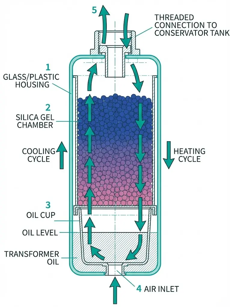
Construction and Oil Cup Function
Standard breathers feature a transparent glass or plastic chamber containing replaceable or regenerable silica gel cartridges. The oil cup at the breather base provides a secondary moisture barrier—incoming air bubbles through a shallow pool of clean transformer oil before reaching the gel chamber.
Oil cup maintenance is critical. An empty or contaminated cup allows unfiltered air to bypass the system. Fill with the same specification oil used in the main tank.
Breather Selection Criteria
Maintenance Reality
Silica gel color indicates moisture saturation status. Fresh gel appears blue or orange depending on indicator type; saturated gel turns pink or colorless.
Replacement frequency varies dramatically by climate:
Regeneration by heating gel to 120–150°C restores adsorption capacity for 3–5 cycles before replacement becomes necessary. Document regeneration history to track gel degradation over time.
Beyond individual device specifications, successful transformer protection depends on proper integration between accessories and the broader protection system.
Standards Compliance Verification
Request documentation demonstrating compliance with applicable standards:
No single international standard governs all transformer accessories. Some manufacturers reference regional standards or internal specifications—verify these provide equivalent protection levels.
Factory Wiring and Terminal Compatibility
Confirm these integration points before shipment:
Incompatible terminal arrangements discovered during commissioning cause costly delays and field modifications.
Spare Parts and Long-Term Availability
Transformer accessories require periodic maintenance over 25–30 year asset lifecycles. Verify:
Proprietary components from discontinued product lines create maintenance headaches decades after installation.
XBRELE supplies oil-immersed distribution transformers with factory-installed, tested accessory packages configured to project requirements. Standard configurations include Buchholz relay, pressure relief device, winding temperature indicator, oil temperature indicator, and silica gel breather with oil cup—all shipped with calibration documentation and test certificates.
Engineering support is available for accessory specification matching, particularly for installations with non-standard environmental conditions or protection scheme requirements. Custom configurations accommodate altitude derating, extreme temperature ranges, and interface compatibility with existing substation control systems.
Contact our technical team as a trusted distribution transformer manufacturer for transformer quotations with complete accessory specifications matched to your project requirements.
Q: What causes a Buchholz relay to give false alarms?
A: Air entrapped during oil filling, improper relay mounting angle exceeding 3° deviation from horizontal, and external vibration from nearby equipment are the most common causes. Proper commissioning procedures including complete air evacuation and mounting verification prevent most false indications.
Q: How do I know when silica gel needs replacement?
A: Monitor the color change indicator—blue or orange gel turning pink or colorless signals moisture saturation. In humid climates, expect 6–12 month replacement intervals; arid environments may allow 2–3 years between changes. Replace when approximately two-thirds of visible gel has changed color.
Q: Can WTI function without the current transformer connection?
A: The WTI will display oil temperature only, not simulated winding hotspot temperature. Without CT-fed heater current, the thermal image function is disabled and readings will underestimate actual winding temperature by 15–30°C during loaded conditions. This defeats the purpose of winding temperature monitoring.
Q: What is the typical service life of transformer accessories?
A: Buchholz relays and temperature indicators typically last 20–25 years with periodic calibration verification. PRD seals may require replacement every 10–15 years depending on material degradation. Silica gel breathers need cartridge replacement based on saturation rather than calendar time.
Q: Should I specify self-resealing or frangible disc PRDs?
A: Self-resealing PRDs allow transformer re-energization after minor overpressure events following inspection. Frangible disc types require replacement after any activation but provide more reliable opening at precise pressure settings. Critical substations often specify self-resealing types to minimize outage duration.
Q: Are accessory contact ratings standardized across manufacturers?
A: Contact voltage and current ratings vary by manufacturer and model. Common ratings include 250V AC at 0.5–1.0A for alarm contacts and 250V AC at 1.0–2.0A for trip contacts. Always verify ratings match your relay panel input specifications before procurement to avoid interface incompatibility.
Q: How do I verify accessory quality when comparing bids?
A: Request factory type test certificates, material certifications for oil-wetted components, and calibration documentation with traceability to national metrology standards. Suppliers unable to provide this documentation may be offering uncertified or counterfeit products that compromise protection reliability.