Need Full Specifications?
Download our 2025 Product Catalog for detailed drawings and technical parameters of all switchgear components.
Get CatalogDownload our 2025 Product Catalog for detailed drawings and technical parameters of all switchgear components.
Get CatalogDownload our 2025 Product Catalog for detailed drawings and technical parameters of all switchgear components.
Get Catalog
Vacuum circuit breaker misapplication causes more field failures than manufacturing defects. Across medium-voltage installations, approximately 35% of VCB-related problems trace back to specification gaps—decisions that seemed reasonable during procurement but missed critical application parameters.
The technology itself is robust. Modern vacuum interrupters routinely achieve 20–30 years of service when properly matched to their operating environment. What fails is the alignment between breaker capability and actual system demands.
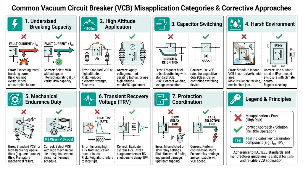
Selection errors cluster into three categories:
Electrical mismatches: Breaking capacity undersized for prospective fault current. Voltage rating inadequate for system transients. TRV capability exceeded by actual recovery voltage profiles.
Environmental oversights: Altitude derating ignored. Humidity and contamination underestimated. Temperature extremes beyond rated ambient range.
Operational misjudgments: Duty cycle demands exceeding mechanical endurance class. Load characteristics not matched to breaker design. Protection coordination assumptions misaligned with actual clearing times.
A single VCB failure in a continuous process plant costs $50,000–$500,000 in lost production—far exceeding the price difference between correctly specified and inadequate equipment.
For foundational understanding of VCB operation, see: What is a Vacuum Circuit Breaker: Working Principle Explained.
Specifiers calculate present-day fault levels and select a VCB with matching capacity. The installation works—initially.
Five years later, the utility upgrades the upstream transformer from 20 MVA to 31.5 MVA. Fault current at the bus jumps from 18 kA to 27 kA. The installed 25 kA breaker now operates in an under-rated condition.
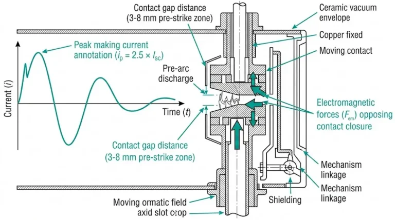
The physics of under-rated interruption:
When a VCB interrupts current exceeding its rated short-circuit breaking capacity, arc energy surpasses design limits. The vacuum interrupter’s CuCr contact material erodes faster than intended—field testing shows accelerated erosion rates of 40–60% when breakers repeatedly interrupt currents near or above their maximum rating.
The contact gap may fail to achieve adequate dielectric recovery. If the vacuum gap cannot hold the transient recovery voltage, re-ignition occurs. Mechanical stress on the operating mechanism intensifies simultaneously: latch integrity, spring fatigue, and frame stress all compound.
Prevention strategy:
Design for the 15–20 year horizon. Obtain utility growth projections and factor in planned generation additions, transformer upgrades, and parallel feeder installations.
Apply a minimum 20% margin above calculated maximum fault current. If system studies show 22 kA prospective fault current, specify 31.5 kA rated breaking capacity—not 25 kA.
Request short-circuit study updates whenever upstream infrastructure changes.

For detailed guidance on matching ratings to applications: Vacuum Circuit Breaker Ratings Explained.
[Expert Insight: Fault Current Margin Calculation]
- Industry practice suggests 20–25% margin above maximum calculated fault current
- Transformer impedance tolerance alone can cause ±10% fault current variation
- Parallel feeder additions typically increase bus fault levels by 15–30%
- Re-evaluate fault studies every 5 years or after any upstream system modification
A mining operation at 3,200 meters specifies standard VCBs rated for 1,000-meter service. Procurement focuses on voltage class and breaking capacity. Altitude correction never enters the discussion.
Why altitude matters:
Air density decreases approximately 11% per 1,000 meters above sea level. This reduction directly affects external dielectric strength—creepage and clearance distances designed for sea-level air density provide reduced insulation margin at altitude. Surface flashover risk increases proportionally.
Heat dissipation suffers as well. Thinner air carries less heat from current-carrying components. Temperature rise in main circuits, auxiliary contacts, and control coils increases beyond nameplate assumptions.
Per IEC 62271-1, standard ratings apply up to 1,000 meters. Above this threshold, derating or enhanced insulation designs become mandatory.
Altitude derating reference:
| Installation Altitude | Voltage Derating Factor | Action Required |
|---|---|---|
| 0–1,000 m | 1.00 (no derating) | Standard specification |
| 1,000–2,000 m | 0.95–0.90 | Enhanced insulation or derating |
| 2,000–3,000 m | 0.90–0.80 | Custom engineering review |
| >3,000 m | <0.80 | Manufacturer consultation required |
[VERIFY STANDARD: IEC 62271-1 altitude derating factors—confirm current edition values]
Prevention strategy:
Specify exact installation altitude in procurement documents. For altitudes exceeding 1,000 meters, request VCBs with enhanced insulation (extended creepage, higher BIL rating) or apply voltage derating per IEC guidelines.
For altitudes above 3,000 meters, standard catalog products rarely suffice. Contact manufacturers directly with complete site environmental data.

A general-purpose VCB rated for “normal” duty gets assigned to switch a 5 Mvar capacitor bank. Operations notices increasing contact wear, occasional pre-strikes during closing, and nuisance protection trips within 18 months.
The capacitor switching challenge:
Capacitor bank energization creates inrush currents 15–20 times higher than steady-state current, with frequencies reaching 2–5 kHz. De-energization produces restrike hazards as contacts separate while voltage across the gap oscillates.
Standard VCBs lack controlled closing mechanisms that synchronize contact closure with voltage zero-crossing. They also lack enhanced restrike resistance—capacitor-class VCBs incorporate contact materials and gap geometries optimized for capacitive load TRV profiles.
Duty class comparison:
| Parameter | Class C1 | Class C2 |
|---|---|---|
| Restrike probability | Low | Very low |
| Capacitor switching suitability | Limited | Recommended |
| Contact material optimization | Standard | Enhanced for capacitive TRV |
| Application | Occasional capacitor switching | Dedicated capacitor bank duty |
Prevention strategy:
Always classify load type during specification. For capacitor switching duty, specify VCBs tested per IEC 62271-100 Class C2. Consider controlled switching devices (point-on-wave controllers) for banks exceeding 2 Mvar.
A water treatment plant specifies indoor-rated VCBs for a “switchgear room.” The room has louvered ventilation, no climate control, and sits adjacent to chemical storage. Humidity regularly exceeds 95%. Chlorine traces permeate the air.
Environmental degradation mechanisms:
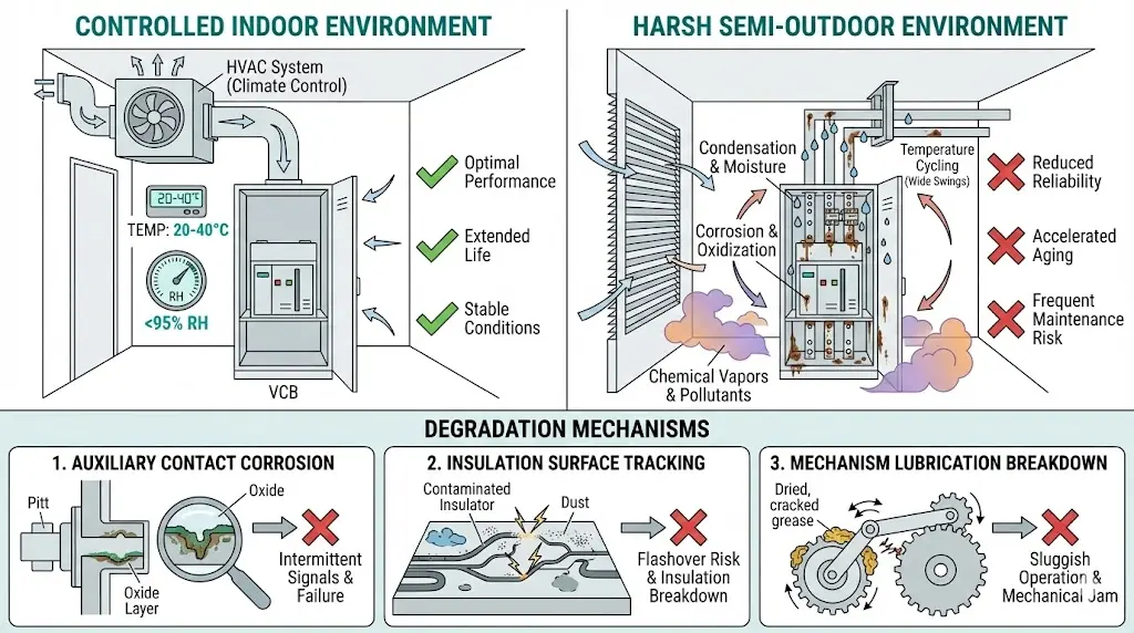
Indoor VCB designs assume controlled environments: ambient temperature –5°C to +40°C, relative humidity ≤95% non-condensing, atmosphere free from corrosive gases and excessive dust.
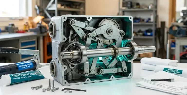
When these assumptions fail, corrosion attacks auxiliary components—control wiring terminals, secondary disconnect contacts, mechanism linkages. Conductive deposits accumulate on epoxy housings, reducing surface resistivity and increasing tracking and flashover risk. High humidity accelerates grease breakdown in operating mechanisms, causing closing and opening times to drift outside tolerance.
Environment assessment checklist:
Prevention strategy:
Characterize the actual environment—not the building classification. For harsh indoor environments, consider outdoor-rated VCBs installed indoors, sealed climate-controlled enclosures with positive pressure, or corrosion-resistant treatments.
For comprehensive environment-based selection guidance: Indoor vs. Outdoor VCB Selection Guide.
[Expert Insight: Environmental Classification Reality Check]
- A “switchgear room” without HVAC is NOT an indoor environment per IEC definitions
- Coastal installations within 1 km of saltwater require enhanced corrosion protection
- Chemical plants should assume corrosive atmosphere unless air quality testing proves otherwise
- Temperature cycling causes condensation even when average humidity appears acceptable
A VCB protecting a 2,000 kW ball mill drive is specified based on full-load current and short-circuit ratings. The drive starts 8–12 times daily. Within 18 months, the VCB exhibits sluggish operation and contact resistance increases.
Cumulative wear effects:
Motor starting imposes repeated high-current stress. A 2,000 kW motor at 6.6 kV draws approximately 200 A at full load—but starting current reaches 1,200–1,400 A for 8–15 seconds per start.
A motor starting 10 times daily for 20 years executes 73,000 start cycles. Each cycle exercises springs, latches, and linkages while thermal cycling stresses primary conductors and contacts.
Mechanical endurance class selection:
| Class | Rated Operations | Typical Application |
|---|---|---|
| M1 | 2,000 | Infrequent switching, fault protection only |
| M2 | 10,000 | Regular switching, motor starting duty |
Prevention strategy:
Calculate cumulative duty over equipment lifetime. For high-cycle motor applications, specify M2 class breakers. Alternatively, use vacuum contactors (rated 100,000+ operations) for routine switching with VCB reserved for fault protection only.
A VCB rated 31.5 kA at 12 kV is installed where transformer-limited faults produce steep TRV wavefronts. The breaker successfully interrupts the current—then immediately restrikes due to inadequate dielectric recovery.
TRV fundamentals:
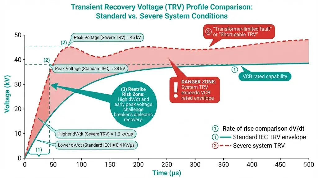
Transient recovery voltage is the voltage appearing across breaker contacts immediately after current zero. Its rate of rise (dV/dt) and peak magnitude determine whether the vacuum gap successfully holds off re-ignition.
IEC 62271-100 defines standard TRV envelopes. However, actual system TRV can exceed these envelopes when transformer-limited faults occur close to VCB terminals, short cable lengths provide minimal surge impedance damping, or reactor switching produces oscillatory TRV with multiple peaks.
Prevention strategy:
Request TRV capability data from manufacturers. Compare against system-specific TRV studies, not just standard IEC envelopes. For critical applications, conduct electromagnetic transient (EMT) studies to characterize worst-case TRV profiles.
Consider TRV mitigation measures: surge capacitors across VCB terminals, RC snubbers, or coordination with system grounding design.
Before finalizing any VCB specification, verify these parameters:
| Parameter | Verification Item | Common Error |
|---|---|---|
| System voltage | Rated voltage ≥ maximum system voltage including contingencies | Ignoring voltage regulation range |
| Fault current | Breaking capacity ≥ prospective fault + 20% margin | Using present-day values only |
| Altitude | Derating applied for installations >1,000 m | Assuming sea-level ratings apply |
| Environment | Indoor/outdoor rating matches actual conditions | Classifying by building, not conditions |
| Load type | Capacitor/reactor duty class specified | Treating all loads as “normal” |
| Duty cycle | Mechanical endurance matches operation frequency | Ignoring motor starting cycles |
| TRV | Capability verified against system studies | Assuming standard envelopes apply |
| Protection | Clearing time matches coordination studies | Using assumed “instantaneous” values |
Systematic verification at the specification stage prevents the field failures described throughout this article. The cost of thorough engineering review is negligible compared to a single VCB failure in service.
For a comprehensive procurement checklist, see: VCB RFQ Checklist.
For manufacturers offering application engineering support alongside quality VCB products, explore XBRELE’s vacuum circuit breaker solutions.
Q: What causes most VCB failures in industrial applications?
A: Selection errors—particularly undersized breaking capacity and environmental mismatches—account for roughly 35% of VCB field failures, exceeding both manufacturing defects and normal wear-related issues.
Q: How much margin should I add above calculated fault current?
A: A minimum 20–25% margin above maximum prospective fault current provides buffer for system growth, calculation uncertainties, and transformer impedance tolerances that can vary ±10%.
Q: Can standard indoor VCBs operate in high-humidity environments?
A: Standard indoor ratings assume ≤95% relative humidity without condensation; environments with sustained high humidity, temperature cycling, or corrosive atmospheres typically require outdoor-rated equipment or sealed climate-controlled enclosures.
Q: How do I know if my application needs Class C2 capacitor switching duty?
A: Any dedicated capacitor bank switching application—particularly banks exceeding 2 Mvar or requiring frequent daily switching—should specify Class C2 to minimize restrike probability during de-energization.
Q: What altitude requires VCB derating?
A: Standard VCB ratings apply up to 1,000 meters elevation; installations above this altitude require voltage derating, enhanced insulation designs, or manufacturer-specific engineering review for adequate dielectric performance.
Q: How often should fault current studies be updated?
A: Re-evaluate fault studies every 5 years as standard practice, and immediately after any upstream system changes including transformer upgrades, parallel feeder additions, or utility infrastructure modifications.
Q: What is the typical service life of a properly specified VCB?
A: Modern vacuum circuit breakers achieve 20–30 years of service life when correctly matched to application requirements, with vacuum interrupter contact erosion rates typically 0.1–0.3 mm per 10,000 operations under normal duty.