Need Full Specifications?
Download our 2025 Product Catalog for detailed drawings and technical parameters of all switchgear components.
Get CatalogDownload our 2025 Product Catalog for detailed drawings and technical parameters of all switchgear components.
Get CatalogDownload our 2025 Product Catalog for detailed drawings and technical parameters of all switchgear components.
Get Catalog
XBRELE provides a complete range of oil-immersed transformers covering S11 & S13 fully-sealed distribution units (30–2500 kVA) and 35kV OLTC power transformers for substations and heavy-duty industrial networks. Designed for long service life, low losses and reliable outdoor performance.
Oil Immersed Transformers are essential for a variety of industrial and power distribution applications. XBRELE offers a range of oil-immersed transformers to meet the specific needs of mining, industrial drives, and high-voltage power networks.
Oil Immersed Transformers are built with precision engineering to provide excellent cooling and insulation, ensuring safe and efficient power delivery. Whether it’s for small-scale industrial usage or large-scale power generation, these transformers are built to last and perform under demanding conditions.
For more details on power distribution transformers and specifications, visit our Power Distribution Transformers Pillar Page .
Switch between S11, S13 and 35kV OLTC series to review rated capacities, voltage combinations and key loss parameters for power distribution and substation applications.

S11-M oil-immersed transformers adopt hermetically sealed corrugated tanks, high-permeability cold-rolled silicon steel cores and concentric windings. They are widely used in 10kV and 20kV distribution networks with 30–2500kVA ratings.
Main Technical Parameters (S11-M Series)
| Rated capacity (kVA) | High voltage (kV) | Tap range (%) | Low voltage (kV) | Connection group | No-load loss (W) | Load loss (W) Dyn11/Yyn0 | Impedance voltage (%) | No-load current (%) |
|---|---|---|---|---|---|---|---|---|
| 30 | 10 | ±5 / ±2×2.5 | 0.4 | Dyn11 or Yyn0 | 100 | 600/630 | 4.0 | 1.50 |
| 50 | 10 | ±5 / ±2×2.5 | 0.4 | Dyn11 or Yyn0 | 130 | 870/910 | 4.0 | 1.30 |
| 80 | 10 | ±5 / ±2×2.5 | 0.4 | Dyn11 or Yyn0 | 180 | 1040/1090 | 4.0 | 1.20 |
| 100 | 10 | ±5 / ±2×2.5 | 0.4 | Dyn11 or Yyn0 | 200 | 1250/1310 | 4.0 | 1.10 |
| 125 | 10 | ±5 / ±2×2.5 | 0.4 | Dyn11 or Yyn0 | 240 | 1500/1580 | 4.0 | 1.10 |
| 160 | 10 | ±5 / ±2×2.5 | 0.4 | Dyn11 or Yyn0 | 280 | 1800/1890 | 4.0 | 1.00 |
| 200 | 10 | ±5 / ±2×2.5 | 0.4 | Dyn11 or Yyn0 | 340 | 2200/2310 | 4.0 | 1.00 |
| 250 | 10 | ±5 / ±2×2.5 | 0.4 | Dyn11 or Yyn0 | 400 | 2600/2730 | 4.0 | 0.90 |
| 315 | 10 | ±5 / ±2×2.5 | 0.4 | Dyn11 or Yyn0 | 480 | 3650/3830 | 4.0 | 0.90 |
| 400 | 10 | ±5 / ±2×2.5 | 0.4 | Dyn11 or Yyn0 | 570 | 4300/4520 | 4.0 | 0.80 |
| 500 | 10 | ±5 / ±2×2.5 | 0.4 | Dyn11 or Yyn0 | 680 | 5150/5410 | 4.0 | 0.80 |
| 630 | 10 | ±5 / ±2×2.5 | 0.4 | Dyn11 or Yyn0 | 810 | 6200 | 4.0 | 0.60 |
| 800 | 10 | ±5 / ±2×2.5 | 0.4 | Dyn11 or Yyn0 | 980 | 7500 | 4.5 | 0.60 |
| 1000 | 10 | ±5 / ±2×2.5 | 0.4 | Dyn11 or Yyn0 | 1150 | 10300 | 4.5 | 0.60 |
| 1250 | 10 | ±5 / ±2×2.5 | 0.4 | Dyn11 or Yyn0 | 1360 | 12000 | 4.5 | 0.50 |
| 1600 | 10 | ±5 / ±2×2.5 | 0.4 | Dyn11 or Yyn0 | 1640 | 14500 | 4.5 | 0.50 |
| 2000 | 10 | ±5 / ±2×2.5 | 0.4 | Dyn11 or Yyn0 | 1940 | 18300 | 5.0 | 0.40 |
| 2500 | 10 | ±5 / ±2×2.5 | 0.4 | Dyn11 or Yyn0 | 2290 | 21200 | 5.0 | 0.40 |
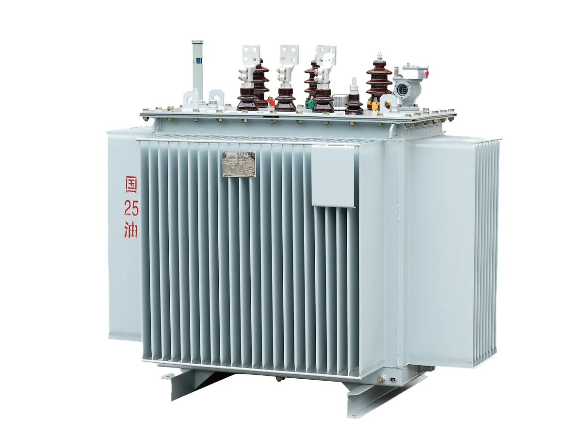
S13-M transformers upgrade the S11 platform with optimized three-column iron cores and tighter loss limits. Compared with the previous generation, no-load loss is reduced by about 30% and noise is lower, while keeping high short-circuit strength and overload capability.
Key Technical Parameters & Loss Data (S13-M)
| Rated capacity (kVA) | High voltage (kV) | Tap range (%) | Low voltage (kV) | Connection group | No-load loss (W) | Load loss (W) Dyn11 / Yyn0 | Impedance voltage (%) | No-load current (%) |
|---|---|---|---|---|---|---|---|---|
| 30 | 10 | ±5 / ±2×2.5 | 0.4 | Dyn11 / Yyn0 | 100 | 600 / 630 | 4.0 | 1.50 |
| 50 | 10 | ±5 / ±2×2.5 | 0.4 | Dyn11 / Yyn0 | 130 | 870 / 910 | 4.0 | 1.30 |
| 80 | 10 | ±5 / ±2×2.5 | 0.4 | Dyn11 / Yyn0 | 180 | 1040 / 1090 | 4.0 | 1.20 |
| 100 | 10 | ±5 / ±2×2.5 | 0.4 | Dyn11 / Yyn0 | 200 | 1250 / 1310 | 4.0 | 1.10 |
| 125 | 10 | ±5 / ±2×2.5 | 0.4 | Dyn11 / Yyn0 | 240 | 1500 / 1580 | 4.0 | 1.10 |
| 160 | 10 | ±5 / ±2×2.5 | 0.4 | Dyn11 / Yyn0 | 280 | 1800 / 1890 | 4.0 | 1.00 |
| 200 | 10 | ±5 / ±2×2.5 | 0.4 | Dyn11 / Yyn0 | 340 | 2200 / 2310 | 4.0 | 1.00 |
| 250 | 10 | ±5 / ±2×2.5 | 0.4 | Dyn11 / Yyn0 | 400 | 2600 / 2730 | 4.0 | 0.90 |
| 315 | 10 | ±5 / ±2×2.5 | 0.4 | Dyn11 / Yyn0 | 480 | 3650 / 3830 | 4.0 | 0.90 |
| 400 | 10 | ±5 / ±2×2.5 | 0.4 | Dyn11 / Yyn0 | 570 | 4300 / 4520 | 4.0 | 0.80 |
| 500 | 10 | ±5 / ±2×2.5 | 0.4 | Dyn11 / Yyn0 | 680 | 5150 / 5410 | 4.0 | 0.80 |
| 630 | 10 | ±5 / ±2×2.5 | 0.4 | Dyn11 / Yyn0 | 810 | 6200 | 4.0 | 0.60 |
| 800 | 10 | ±5 / ±2×2.5 | 0.4 | Dyn11 / Yyn0 | 980 | 7500 | 4.5 | 0.60 |
| 1000 | 10 | ±5 / ±2×2.5 | 0.4 | Dyn11 / Yyn0 | 1150 | 10300 | 4.5 | 0.60 |
| 1250 | 10 | ±5 / ±2×2.5 | 0.4 | Dyn11 / Yyn0 | 1360 | 12000 | 4.5 | 0.50 |
| 1600 | 10 | ±5 / ±2×2.5 | 0.4 | Dyn11 / Yyn0 | 1640 | 14500 | 4.5 | 0.50 |
| 2000 | 10 | ±5 / ±2×2.5 | 0.4 | Dyn11 / Yyn0 | 1940 | 18300 | 5.0 | 0.40 |
| 2500 | 10 | ±5 / ±2×2.5 | 0.4 | Dyn11 / Yyn0 | 2290 | 21200 | 5.0 | 0.40 |
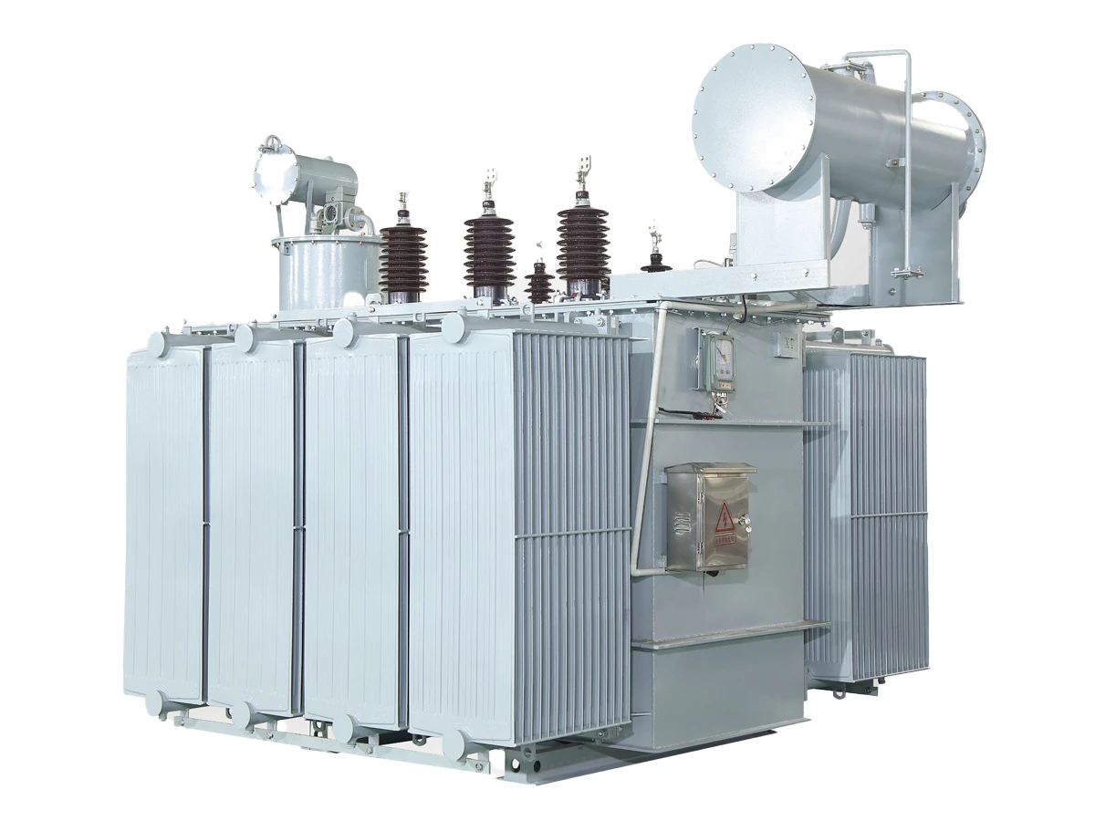
Designed as main step-down units in 35kV substations and industrial power systems, these transformers provide flexible voltage regulation with on-load tap changers and wide capacity coverage from 50kVA up to 31500kVA.
Main Technical Parameters — 35kV OLTC Section 50–2500kVA
| Rated capacity (kVA) | No-load loss (kW) | Load loss (kW) | No-load current (%) | Short-circuit impedance (%) |
|---|---|---|---|---|
| 50 | 0.16 | 1.20 / 1.14 (Dyn11 / Yyn0) | 1.3 | 6.5 |
| 100 | 0.23 | 2.01 / 1.91 | 1.1 | 6.5 |
| 125 | 0.27 | 2.37 / 2.26 | 1.1 | 6.5 |
| 160 | 0.28 | 2.82 / 2.68 | 1.0 | 6.5 |
| 200 | 0.34 | 3.32 / 3.16 | 1.0 | 6.5 |
| 250 | 0.40 | 3.95 / 3.76 | 0.95 | 6.5 |
| 315 | 0.48 | 4.75 / 4.53 | 0.95 | 6.5 |
| 400 | 0.58 | 5.74 / 5.47 | 0.85 | 6.5 |
| 500 | 0.68 | 6.91 / 6.58 | 0.85 | 6.5 |
| 630 | 0.83 | 7.86 | 0.65 | 6.5 |
| 800 | 0.98 | 9.40 | 0.65 | 6.5 |
| 1000 | 1.15 | 11.5 | 0.65 | 6.5 |
| 1250 | 1.40 | 13.9 | 0.60 | 6.5 |
| 1600 | 1.69 | 16.6 | 0.60 | 6.5 |
| 2000 | 1.99 | 19.7 | 0.55 | 6.5 |
| 2500 | 2.36 | 23.2 | 0.55 | 6.5 |
Note: Above data for 50–2500kVA section are based on the manufacturer’s standard OLTC design at 35kV / 10.5kV, Dyn11 or Yyn0 connection.
Main Technical Parameters — 35kV OLTC Overall Range 630–31500kVA
| Item | Parameter | Typical value / range | Remarks |
|---|---|---|---|
| Rated capacity | kVA | 630 – 31500 | Covers 630, 800, 1000, 1250, 1600, 2000, 2500, 3150, 4000, 5000, 6300, 8000, 10000, 12500, 16000, 20000, 25000, 31500. |
| High voltage | kV | 35 / 35–38.5 | Standard 35kV system; some models with extended 35–38.5kV tap range. |
| Tap range (HV) | % | ±2×2.5 / ±5 / +3 ~ −5 | On-load tap changer, tap pattern depends on capacity section. |
| Low voltage | kV | 6.3 / 6.6 / 10.5 | Typical distribution levels for 35kV/10kV substations and feeders. |
| Connection group | — | Dyn11 / Yd11 / YNd11 | Dyn11 for low-voltage 10.5kV section; Yd11 or YNd11 for higher capacities. |
| No-load loss | kW | ≈ 0.83kW (630kVA) – 21.8kW (31500kVA) | See detailed tables in the following high-capacity section or full catalogue. |
| Load loss (75°C) | kW | ≈ 7.86kW (630kVA) – 115kW (31500kVA) | Values vary with capacity and tap position. |
| No-load current | % | 0.25 – 0.65 | Typical range from 35kV OLTC transformer parameter tables. |
| Short-circuit impedance | % | 6.5 / 7.0 / 8.0 / 10.0 | 6.5% for small ratings, 7–8% for medium, 10% for 25–31.5MVA section. |
| Cooling | — | ONAN / ONAF (for larger ratings) | Natural oil-air cooling; forced oil cooling available for high-capacity models. |
| Measuring & protection | — | Oil level gauge, oil temperature indicator, gas relay, Buchholz relay | As described in the structural features section of the catalogue. |
Main Technical Parameters — 35kV OLTC High-Capacity Section 2000–31500kVA
| Rated capacity (kVA) | No-load loss (kW) | Load loss (kW) | No-load current (%) | Short-circuit impedance (%) |
|---|---|---|---|---|
| 2000 | 2.30 | 19.2 | 0.50 | 6.5 |
| 2500 | 2.72 | 20.6 | 0.50 | 6.5 |
| 3150 | 3.23 | 24.7 | 0.50 | 6.5 |
| 4000 | 3.87 | 29.1 | 0.50 | 6.5 |
| 5000 | 4.64 | 34.2 | 0.50 | 6.5 |
| 6300 | 5.63 | 36.7 | 0.50 | 6.5 |
| 8000 | 7.87 | 40.6 | 0.40 | 7.0 |
| 10000 | 9.28 | 48.0 | 0.40 | 7.0 |
| 12500 | 10.9 | 56.8 | 0.35 | 7.0 |
| 16000 | 13.1 | 70.3 | 0.35 | 8.0 |
| 20000 | 15.3 | 82.7 | 0.35 | 8.0 |
| 25000 | 18.3 | 97.8 | 0.30 | 10.0 |
| 31500 | 21.8 | 115 | 0.30 | 10.0 |
Note: High-capacity 35kV OLTC transformers are usually supplied with Yd11 or YNd11 connection, tap ranges ±2×2.5% / ±5%, and cooling type ONAN/ONAF according to project requirements.
XBRELE’s S11/S13/S20 oil-immersed transformers deliver high efficiency, low loss and exceptional durability—ideal for power distribution grids, industrial loads, and substations.
Built with high-grade cold-rolled silicon steel sheets to minimize core loss and improve long-term operating efficiency.
Copper windings with improved mechanical strength help the transformer withstand short-circuit forces during grid faults.
The robust oil-immersed structure ensures stable cooling and long-term safe operation in outdoor or indoor substations.
From core laminations to final routine tests, every XBRELE oil-immersed transformer follows a controlled process to meet IEC/GB standards for long-term grid operation.
Each S11 / S13 / S20 transformer is manufactured on a dedicated line, with clear steps from core cutting to vacuum oil filling to ensure low loss and high reliability.
Cold-rolled silicon steel sheets are sheared and stacked with step-lap joints to reduce no-load loss and noise.
Copper windings are wound under tension, with layered paper/pressboard insulation to withstand thermal and short-circuit stresses.
The active part is placed in a vacuum oven to remove moisture from windings and insulation, improving dielectric strength.
Transformer oil is filled under deep vacuum, ensuring no air bubbles remain in the winding and core gaps.
Fully assembled tanks are pressure-tested and checked for leaks before painting and nameplate installation.
All transformers are tested according to IEC 60076 and GB/T 6451 to verify electrical, mechanical and insulation performance.
Whether you need urgent replacements for a transformer in the field or batch delivery for a new power station, XBRELE ensures that your oil-immersed transformers arrive on time and are ready for installation.
Our manufacturing lines are optimized for quick turnaround of oil-immersed transformers, ensuring your critical installations are met with urgency.
We understand that shipping transformers requires robust protection. Our packaging ensures your equipment survives long-distance transport safely.
Our technical team is always ready to assist with transformer installation and ongoing maintenance requirements.
Here are answers to frequently asked questions about Oil Immersed Transformers, including their benefits, installation, and maintenance.