Need Full Specifications?
Download our 2025 Product Catalog for detailed drawings and technical parameters of all switchgear components.
Get CatalogDownload our 2025 Product Catalog for detailed drawings and technical parameters of all switchgear components.
Get CatalogDownload our 2025 Product Catalog for detailed drawings and technical parameters of all switchgear components.
Get Catalog
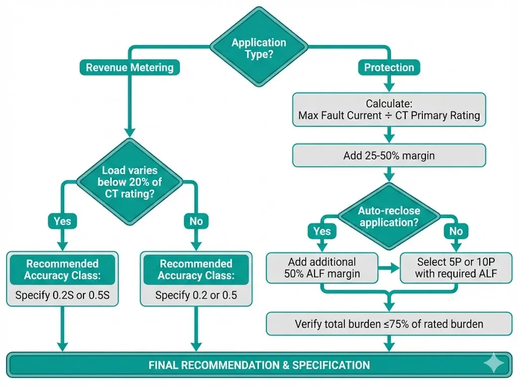
Current transformers serve two fundamentally different purposes in electrical power systems—revenue metering and fault protection. Each application demands specific performance characteristics, which is why CT accuracy classes exist. A metering CT optimized for billing precision at normal load currents will fail during fault conditions. A protection CT designed to perform during 20× overcurrent events lacks the fine accuracy needed for revenue calculations.
This guide breaks down IEC 61869-2 accuracy class designations, explains the technical differences between metering classes (0.1, 0.2, 0.5) and protection classes (5P, 10P), and provides practical selection guidance for medium-voltage applications.
A CT accuracy class is a standardized designation that defines the maximum permissible measurement error under specified operating conditions. The class number directly indicates allowable percentage error at rated current, with additional specifications for phase displacement and behavior during fault conditions.
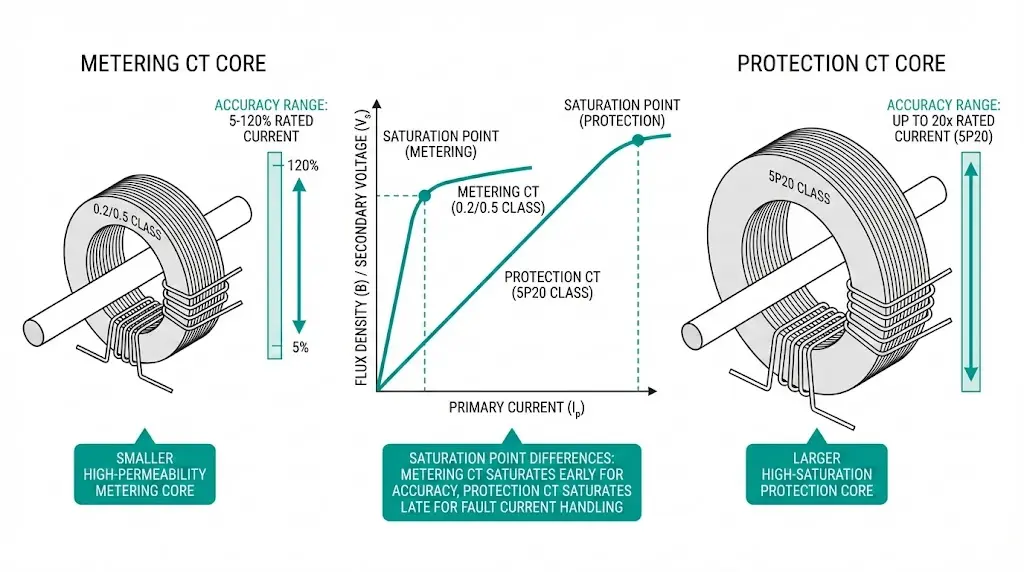
Two distinct classification systems exist. Metering classes (0.1, 0.2, 0.5, 1.0) optimize precision across normal operating currents—typically 5% to 120% of rated current. Protection classes (5P, 10P) prioritize performance during fault conditions, maintaining accuracy at current multiples far exceeding normal operation.
The distinction matters because these requirements conflict physically. Metering accuracy demands high-permeability core materials that saturate quickly during faults. Protection reliability requires larger cores that resist saturation but sacrifice low-current precision. One CT cannot excel at both.
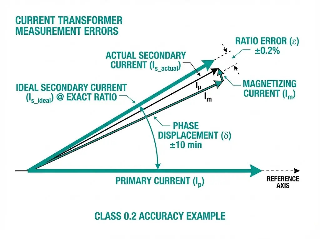
Current transformer errors stem from the magnetizing current required to establish core flux. This current represents energy diverted from the ideal transformation process, creating two measurable deviations.
Ratio error (ε) quantifies the percentage difference between actual and rated transformation ratios. A 1000/5 A CT might actually deliver 4.98 A at 1000 A primary—a 0.4% ratio error. This error varies with primary current magnitude and connected burden.
Phase displacement (δ) measures the angular difference between primary and secondary current phasors, expressed in minutes of arc. Ideal transformation produces zero phase shift; real CTs exhibit small displacements due to magnetizing current requirements.
Core materials significantly influence CT behavior. Grain-oriented silicon steel cores typically operate at maximum flux densities of 1.5–1.8 T (Tesla), while nanocrystalline cores achieve lower losses at flux densities around 1.2 T. The rated burden—expressed in VA (volt-amperes)—determines the maximum load the CT can supply while maintaining accuracy, with standard values ranging from 2.5 VA to 30 VA for metering applications.
Both errors must remain within class-specific limits across the operating range. For Class 0.2 metering CTs, ratio error cannot exceed ±0.2% and phase displacement must stay below ±10 minutes at rated current. Protection classes permit larger errors—up to ±1% ratio error under normal conditions—but maintain these limits at much higher current multiples.
Metering accuracy classes prioritize precision at normal operating currents where billing calculations occur. IEC 61869-2 defines these classes through ratio error and phase displacement limits at multiple test points.
| Class | Ratio Error at 100% In | Phase Displacement | Accuracy Range | Typical Application |
|---|---|---|---|---|
| 0.1 | ±0.1% | ±5 min | 5–120% | Laboratory reference standards |
| 0.2 | ±0.2% | ±10 min | 5–120% | Transmission revenue metering |
| 0.2S | ±0.2% | ±10 min | 1–120% | Variable-load revenue metering |
| 0.5 | ±0.5% | ±30 min | 5–120% | Distribution substation metering |
| 0.5S | ±0.5% | ±30 min | 1–120% | Industrial revenue metering |
| 1.0 | ±1.0% | ±60 min | 5–120% | Indicator instruments |
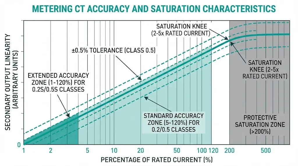
The “S” suffix indicates extended accuracy at low currents. Standard classes maintain specified accuracy from 5% to 120% of rated current. Class 0.2S and 0.5S extend this range down to 1% of rated current—essential for facilities with variable loads where light-load billing accuracy affects revenue.
In commissioning work across industrial facilities, we consistently find that 0.2S specification becomes critical when billing settlements exceed $50,000 monthly. A 0.3% error at 10% load—acceptable for standard 0.5 class but outside 0.2S limits—compounds across billing cycles.
Intentional saturation distinguishes metering cores. These CTs saturate at 2–5× rated current, limiting secondary output during faults. This protects connected meters from damage but renders metering CTs unsuitable for protection applications where fault current accuracy matters.
[Expert Insight: Metering CT Selection]
- Specify 0.2S or 0.5S class when loads regularly drop below 20% of CT rating
- Verify actual connected burden stays below 75% of rated burden for optimal accuracy
- Modern digital meters present <1 VA burden—confirm CT maintains accuracy at light burdens
- Request factory test certificates showing actual measured errors, not just class compliance
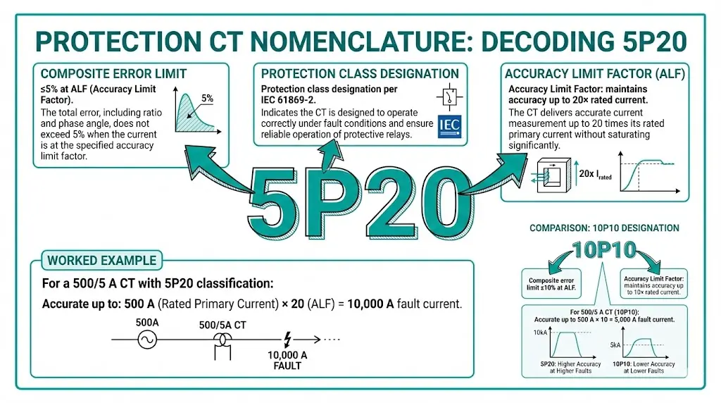
Protection classes follow a different notation system reflecting their primary function: accurate fault current measurement. The designation “5P20” encodes three parameters essential for relay coordination.
| Class | Composite Error at ALF | Common ALF Values | Typical Application |
|---|---|---|---|
| 5P | ≤5% | 10, 15, 20, 30 | Primary protection relays, differential schemes |
| 10P | ≤10% | 10, 15, 20 | Backup protection, overcurrent relays |
The Accuracy Limit Factor determines the maximum fault current multiple where the CT maintains linear output. A 5P20 CT with 1000 A primary rating performs accurately up to 20,000 A primary current. Beyond this threshold, core saturation distorts the secondary waveform, potentially causing relay misoperation.
Protection classes follow a different designation system: the number before “P” indicates the composite error limit as a percentage. A 5P20 class CT allows up to ±5% composite error and maintains accuracy up to 20 times rated current (the Accuracy Limit Factor, or ALF). Protection CTs must accurately reproduce fault currents ranging from 2 kA to 63 kA depending on system requirements.
ALF calculation for proper specification:
Required ALF ≥ Maximum Fault Current ÷ CT Rated Primary Current
For a 12.5 kA fault level with 500/5 A CTs:
Required ALF ≥ 12,500 ÷ 500 = 25
A 5P20 rating falls short; specify 5P30 to provide adequate margin.
Protection cores use larger cross-sections and higher-saturation materials compared to metering cores. This delays magnetic saturation, ensuring relays receive accurate fault current signals. The trade-off: reduced precision at normal operating currents, typically ±1% ratio error versus ±0.2% for metering classes.
The fundamental design philosophies conflict. Understanding these differences prevents misapplication.
| Parameter | Metering CT | Protection CT |
|---|---|---|
| Primary function | Revenue billing, energy monitoring | Fault detection, relay operation |
| Accuracy range | 1–120% of rated (S class) | Up to ALF × rated current |
| Error specification | Ratio error + phase displacement | Composite error |
| Saturation behavior | Early (2–5× rated)—protective | Delayed (up to ALF × rated)—essential |
| Core design | Smaller, high-permeability steel | Larger, high-saturation materials |
| Typical classes | 0.2, 0.2S, 0.5, 0.5S, 1.0 | 5P10, 5P20, 10P10, 10P15 |
| Connected devices | kWh meters, power analyzers | Protection relays, fault recorders |
During fault analysis at a manufacturing facility, we observed a 0.5 class metering CT delivering only 15% of actual fault current to the relay during a 12 kA fault. The metering core saturated almost immediately, collapsing the secondary output while the fault persisted. Relay operation was delayed by 150 ms—long enough to cause upstream coordination failure.
This scenario illustrates why separate cores serve metering and protection functions in properly designed installations.
Connected burden directly affects CT accuracy. Exceeding rated burden degrades metering precision and reduces effective ALF for protection CTs.
Lead burden calculation:
Lead VA = I²secondary × 2 × Rlead
For 5 A secondary with 50 m cable run (2.5 mm² copper, ~0.35 Ω one-way):
Lead VA = 25 × 2 × 0.35 = 17.5 VA
This explains why 1 A secondaries suit long cable runs—burden reduces by 25× compared to 5 A secondaries for identical cable.
Selection checklist:
[Expert Insight: Protection CT Specification]
- Auto-reclose applications require 50% additional ALF margin due to remanent flux effects
- Differential protection schemes demand matched CT characteristics—specify identical knee-point voltages
- Modern numerical relays present <1 VA burden versus 15–30 VA for electromechanical types—recalculate effective ALF
- Request excitation curves from manufacturers to verify knee-point voltage meets relay requirements
Most medium-voltage installations require both metering and protection from each feeder. Dual-core (or multi-core) CTs address this by incorporating separate magnetic cores wound on the same primary conductor.
Typical dual-core specification:
Each core undergoes independent testing per IEC 61869-2. The metering core maintains billing accuracy at normal currents while saturating during faults. The protection core preserves fault current fidelity for relay operation. Neither compromises the other’s function.
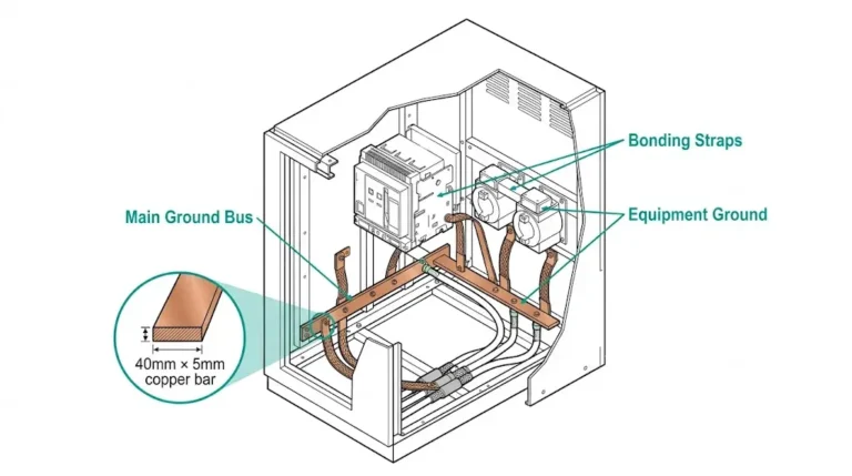
Integration with medium-voltage vacuum circuit breakers requires coordinated CT specification. The CT accuracy limit factor must exceed the breaker’s rated breaking capacity to ensure protection relays receive accurate signals throughout the fault clearing sequence. For switchgear assemblies, component manufacturers typically provide CT recommendations matched to specific breaker ratings.
When specifying CTs for new installations, provide the following to your supplier:
Field experience across 75+ substation commissioning projects reveals recurring specification mistakes.
A 0.5 class CT saturates during faults, delivering distorted signals to protection relays. Trip times extend; coordination fails.
Solution: Always specify dedicated protection cores with ALF exceeding maximum fault current ÷ CT primary rating.
Long cable runs to relay rooms add significant VA load, particularly with 5 A secondaries.
Solution: Calculate lead burden using actual cable resistance. Consider 1 A secondary for runs exceeding 30 m.
Unequal CT characteristics create false differential current, causing spurious trips or failure to operate.
Solution: Specify identical CT ratios, accuracy classes, and knee-point voltages for all CTs in differential zones.
After initial fault clearing, residual magnetization remains in the core. Upon reclose to a persistent fault, this remanence causes earlier saturation.
Solution: Specify 50% higher ALF for auto-reclose applications, or use anti-remanence core designs.
Understanding vacuum circuit breaker ratings helps coordinate CT specifications with breaker capabilities—the CT must maintain accuracy throughout the breaker’s rated breaking current range.
The designation indicates a protection-class CT maintaining composite error below 5% up to 20 times rated primary current. At a 400/5 A rating, this CT provides accurate fault current measurement up to 8,000 A before core saturation compromises output.
This configuration risks protection failure. Metering cores saturate at 2–5× rated current, collapsing secondary output precisely when relays need accurate fault signals. Separate protection cores with appropriate ALF ratings are essential for reliable fault detection.
Choose 0.2S when loads regularly operate below 20% of CT rating. Standard 0.2 class guarantees accuracy only from 5–120% of rated current; 0.2S extends this to 1–120%, maintaining billing precision during light-load periods.
Operating below rated burden increases effective ALF—a 5P20 CT at half burden performs similarly to 5P40. However, some CT designs exhibit increased errors at very light burdens. Verify actual burden falls between 25% and 100% of rated burden for predictable performance.
Knee-point voltage indicates the secondary voltage where core magnetization becomes non-linear—specifically, where a 10% voltage increase produces 50% magnetizing current increase. Protection relays require CTs with knee-point voltage exceeding the secondary voltage developed during maximum fault conditions to ensure accurate measurement.
IEC 61869-2 uses decimal metering classes (0.2, 0.5) and P-designated protection classes (5P, 10P). IEEE C57.13 specifies metering classes as 0.3 and 0.6, with protection classes designated by secondary terminal voltage capability (C100, C200). For international projects, specify IEC classes to avoid conversion ambiguity.
Capacitor protection requires accurate measurement of relatively small unbalance currents rather than high fault currents. Class 5P10 typically provides adequate ALF, while the metering core (if dual-core) should be 0.5 class or better for capacitor current monitoring and harmonic analysis.
For CT specification support matched to your switchgear requirements, contact XBRELE’s engineering team via the technical contact page. We provide integrated solutions combining vacuum interrupter technology with properly coordinated instrument transformers for reliable metering and protection performance, including relay coordination checks for transformer feeders.
External Reference: IEC 61869-2:2012 Instrument Transformers – Additional Requirements for Current Transformers