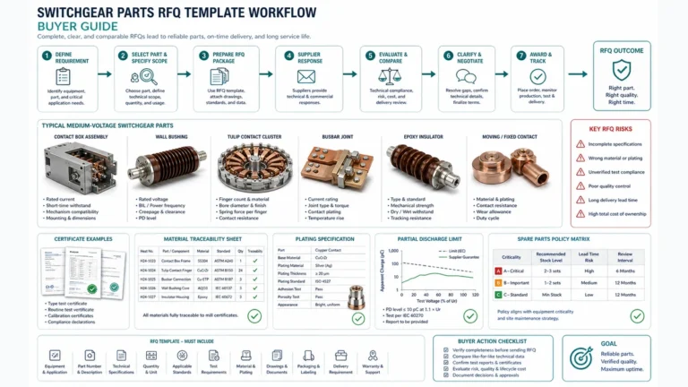
Need Full Specifications?
Download our 2025 Product Catalog for detailed drawings and technical parameters of all switchgear components.
Get CatalogDownload our 2025 Product Catalog for detailed drawings and technical parameters of all switchgear components.
Get CatalogDownload our 2025 Product Catalog for detailed drawings and technical parameters of all switchgear components.
Get Catalog
Electromagnetic compatibility (EMC) failures in control wiring cause false trips that halt production, frustrate operators, and erode confidence in protection systems. A vacuum circuit breaker opens unexpectedly—yet the relay logs no fault. The culprit is invisible: electromagnetic interference (EMI) injecting noise into low-voltage control circuits. This guide explains the physics behind EMI coupling, then delivers practical suppression, grounding, and routing techniques proven across 60+ medium-voltage switchgear installations.
Control wiring noise refers to unwanted electrical disturbances that corrupt low-voltage signals, triggering false trips, nuisance alarms, and equipment malfunctions. EMC encompasses the principles enabling devices to operate without interference from—or causing interference to—adjacent equipment.
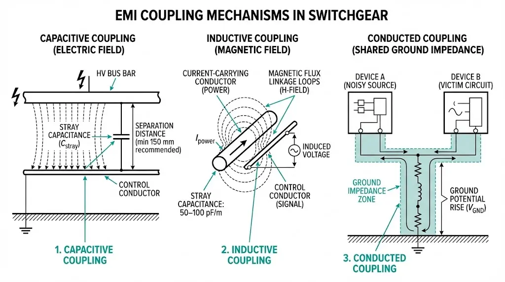
The physics of EMI involves three coupling mechanisms:
According to IEC 61000-4-4 (Electrical Fast Transient/Burst Immunity), industrial control equipment must withstand transient disturbances up to 4 kV on signal and power ports for harsh environments. Field measurements in mining substations reveal noise amplitudes reaching 2–5 V peak on unshielded control cables routed parallel to VFD output conductors—far exceeding the 50–100 mV sensitivity thresholds of modern protective relays.
Noise sources in vacuum circuit breaker control systems include switching transients with rise times under 5 ns, contactor arc-induced oscillations at 1–10 MHz, and VFD common-mode noise at carrier frequencies between 2–16 kHz.
Three primary EMI sources dominate industrial environments. Identifying each is essential before selecting suppression strategies.
Switching Transients
When circuit breakers, contactors, or relays operate, they generate high-frequency voltage transients propagating through control wiring via conducted and radiated pathways. During contactor switching, transient voltages can reach 2,500 V with rise times under 5 ns. These fast transients couple capacitively into adjacent control cables, creating common-mode noise that triggers spurious relay operations.
Variable Frequency Drive Emissions
VFDs generate broadband EMI through PWM switching, typically at carrier frequencies between 2–16 kHz. The resulting harmonic content extends into the MHz range. Testing in manufacturing facilities showed that unshielded control cables routed within 300 mm of VFD output conductors experienced induced noise levels exceeding 50 mV—sufficient to cause erratic PLC input readings and false protection operations.
Common noise sources in switchgear installations include:
Inductive Load Back-EMF
Motor starters, solenoid valves, and transformer auxiliaries create back-EMF spikes during de-energization. Without suppression, relay coils rated at 24 VDC can generate transients exceeding 500 V peak. These spikes propagate through shared ground paths and power supply rails, affecting sensitive control circuits throughout the installation.
[Expert Insight: Field Observations on Noise Severity]
- Installations near arc furnaces or large motor drives require enhanced EMC measures—expect 3–5× higher induced noise than typical industrial environments
- Control cables acting as unintentional antennas show dramatically increased coupling when lengths approach quarter-wavelength multiples of interference frequencies
- Ground potential rises of 50–200 V during fault conditions can damage optocouplers rated for 1 kV isolation
Suppression devices form the first defense layer against EMI-induced false trips. Three suppressor types serve distinct functions in vacuum contactor coil protection and relay circuits.
Suppressor Comparison
| Suppressor Type | Response Time | Energy Handling | Best Application |
|---|---|---|---|
| Metal-Oxide Varistor (MOV) | ~25 ns | High (joules) | Trip/close coil protection |
| TVS Diode | <1 ns | Low–Medium | Sensitive relay inputs, IED ports |
| RC Snubber | N/A (passive) | Continuous | Across inductive coils to damp ringing |
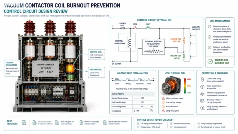
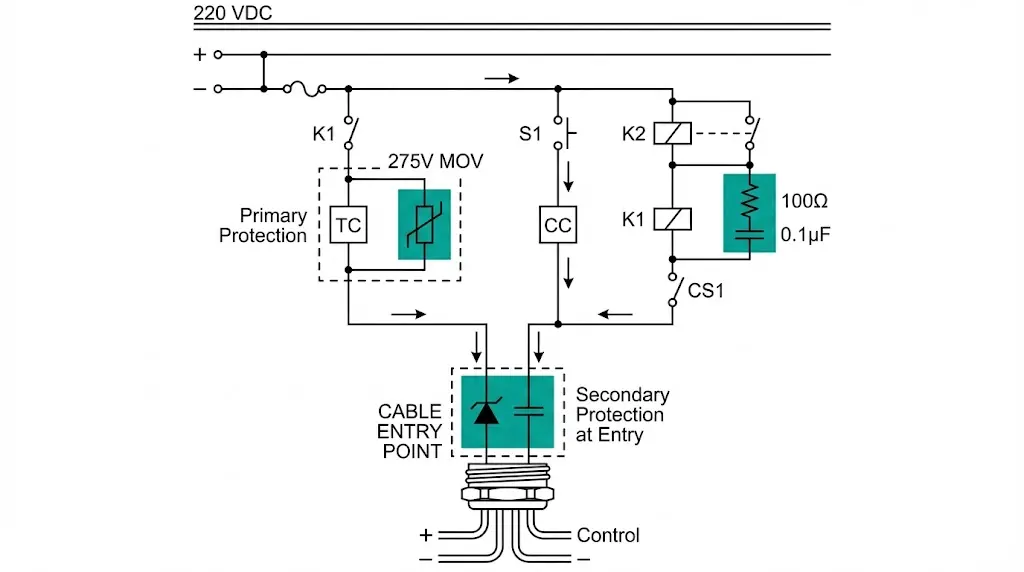
RC Snubber Sizing for 220 VDC Trip Coils
The sizing formula C ≈ I²/(10 × V) yields typical values of 0.1 µF film capacitor plus 100 Ω resistor (2 W minimum). Capacitor voltage rating must exceed 1.5× supply—minimum 330 VDC for 220 VDC circuits.
Placement Rules
Install suppressors directly across every inductive load: trip coils, closing coils, auxiliary relays. Add secondary protection at the relay-compartment cable entry point. Never install suppressors only at the power supply end—the cable between supply and load acts as an antenna, picking up interference after the suppressor.
Proper grounding eliminates the common-impedance coupling that creates ground loops—a leading cause of persistent false trips.
Why Daisy-Chain Grounding Fails
Multiple ground connections create loops. Circulating currents during transients induce differential voltages on control circuits. The symptom: intermittent false trips correlating with adjacent feeder operations but never captured by fault recorders.
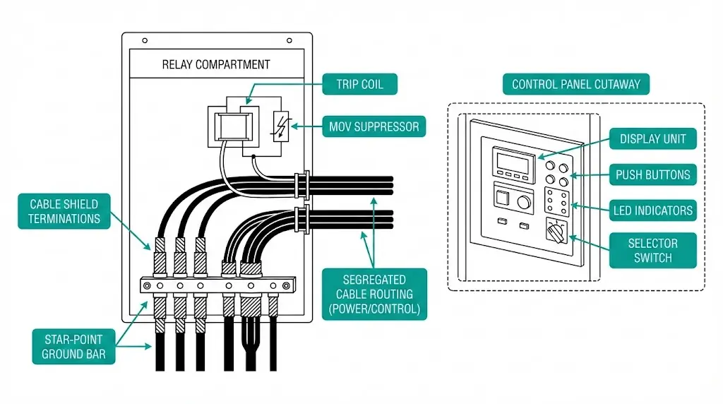
Implementing Single-Point (Star) Grounding
Shield Termination Best Practices
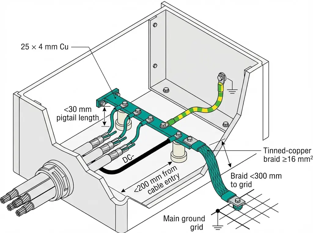
Use 360° EMC glands with ferrule contact for optimal shield connection. If glands are unavailable, keep pigtail length under 30 mm—shorter always performs better. Never use the shield as a signal return conductor.
Ground-Bar to Main Grid Connection
Use ≥16 mm² flexible tinned-copper braid with length under 300 mm. At high frequencies, inductance matters more than resistance. Bond to the switchgear ground grid, not random structural steel.
[Expert Insight: Grounding Mistakes We See Repeatedly]
- Shield pigtails exceeding 150 mm defeat shielding effectiveness above 1 MHz
- Connecting DC-negative to PE at multiple points creates ground loops that amplify 50/60 Hz noise
- Flexible braid connections corrode in humid environments—specify tinned copper and inspect annually
- Ground bar location matters: mount within 200 mm of cable entry to minimize lead inductance
Physical separation between power and control conductors prevents capacitive and inductive coupling at the source—often more effective than after-the-fact suppression.
Minimum Separation Distances
Maintain at least 100 mm between control and power cables in standard environments. Near VFD output cables, increase separation to 300 mm minimum due to high-frequency PWM noise content. When crossing is unavoidable, cross at 90° only—never run parallel in the same cable tray.
Shielded Cable Selection
Cable Entry Discipline
EMC cable glands with 360° ferrule contact provide superior shield termination for new installations. For retrofit situations, ferrite snap-on cores at entry points offer practical noise reduction—select cores with impedance optimized for the 1–30 MHz range where most switching transients concentrate.
Segregate gland plates physically: power cable entry on one side of the enclosure, control cable entry on the opposite side.
Testing validates that suppression, grounding, and routing measures actually work under operational conditions.
Pre-Commissioning Immunity Tests
When test equipment is available, apply standardized immunity tests per IEC 61000-4-4 electrical fast transient immunity:
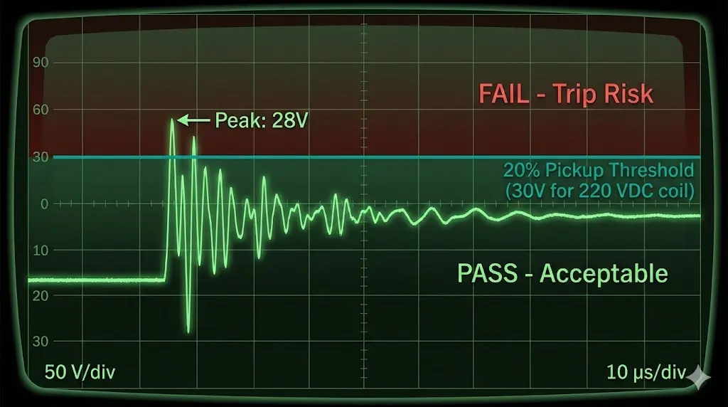
On-Site Oscilloscope Method
Most sites lack EMC test generators. A portable oscilloscope provides practical verification:
For a 220 VDC trip coil with 70% pick-up threshold (154 V), acceptable noise is approximately 30 V peak.
Documenting Baseline Performance
Record waveforms during worst-case operations: capacitor bank switching, motor starting, fault clearing. Archive as commissioning evidence and future troubleshooting reference.
Situation
A mining site experienced unexplained VCB trips on an 800 kW crusher feeder every 3–7 days. No fault codes appeared. Manual reset restored operation, but production losses accumulated.
Investigation Findings
Corrective Actions
Result
Zero false trips over 14-month monitoring period. The integrated approach—addressing routing, suppression, and grounding together—succeeded where previous single-point fixes had failed.
XBRELE switchgear components incorporate EMC-ready design from the factory:
Request product datasheets or schedule an EMC consultation with XBRELE engineers to address persistent false trip issues in your switchgear installations.
Q1: What causes false trips in medium-voltage switchgear without recorded faults?
A: Electromagnetic interference couples into control wiring and injects noise voltages that exceed trip-coil pickup thresholds, causing the breaker to operate even though no power system fault exists.
Q2: How do I determine if EMI is causing my nuisance trips?
A: Measure differential noise across trip-coil terminals with an oscilloscope during adjacent equipment operations; noise exceeding 20% of the coil’s minimum pickup voltage indicates EMI-induced trip risk.
Q3: Should I use MOVs or TVS diodes for trip coil protection?
A: MOVs suit trip and closing coils because they absorb higher transient energy; TVS diodes respond faster but handle less energy, making them better for sensitive IED input protection.
Q4: Why does daisy-chain grounding cause problems in control circuits?
A: Multiple ground points create loops where circulating currents during transients induce differential voltages on signal conductors, defeating the noise rejection that proper grounding should provide.
Q5: How much separation is needed between control and VFD output cables?
A: Maintain at least 300 mm separation from VFD output cables due to high-frequency PWM harmonic content; standard power cables require minimum 100 mm separation from control conductors.
Q6: Can ferrite cores fix EMI problems without rewiring?
A: Ferrite snap-on cores provide practical noise reduction for retrofit situations, particularly effective against interference in the 1–30 MHz range, though they work best combined with proper grounding rather than as standalone solutions.
Q7: How often should EMC measures be inspected after installation?
A: Inspect shield terminations, suppressor condition, and ground connections annually; flexible braid connections in humid environments may require more frequent verification due to corrosion risk.
Markdown selection80 字符68 字数0 行数第 1 行, 第 1 列
HTML 12517 字数140 段落
导入/导出