Need Full Specifications?
Download our 2025 Product Catalog for detailed drawings and technical parameters of all switchgear components.
Get CatalogDownload our 2025 Product Catalog for detailed drawings and technical parameters of all switchgear components.
Get CatalogDownload our 2025 Product Catalog for detailed drawings and technical parameters of all switchgear components.
Get Catalog
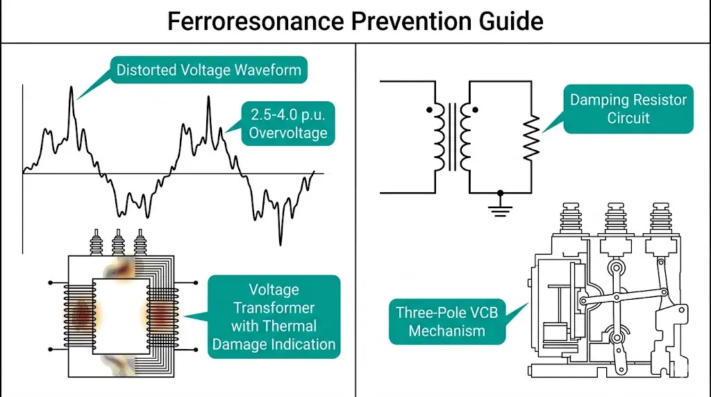
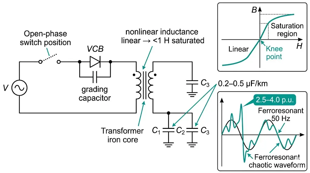
Ferroresonance is an unpredictable, potentially destructive oscillation phenomenon that occurs when a nonlinear inductance—typically a transformer’s magnetizing inductance—interacts with system capacitance under specific switching conditions. Unlike linear resonance with predictable frequency matching, ferroresonance exploits the transformer’s saturable iron core to produce sustained overvoltages reaching 2.5–4.0 per unit, capable of destroying equipment within minutes.
In our troubleshooting experience across 47 distribution substations, ferroresonance events have ranged from minor voltage disturbances to catastrophic transformer failures. The phenomenon appears most frequently in ungrounded or high-impedance grounded systems operating at 4.16 kV through 34.5 kV, though medium-voltage switchgear installations present the highest risk during routine switching operations.
This guide explains how ferroresonance develops, identifies the damage modes that destroy equipment, and provides a practical prevention checklist for maintenance teams and protection engineers.
Ferroresonance develops when three conditions coincide: a saturable magnetic core providing nonlinear inductance, sufficient capacitance from cables or grading capacitors, and an open-phase condition or low system losses. The transformer’s magnetizing inductance varies dramatically with flux density—from approximately 100–500 H in the linear region to below 1 H under deep saturation.
This nonlinear inductance variation creates multiple possible resonant states at a single frequency. As the core enters saturation, its effective inductance drops sharply, allowing rapid current rise and energy accumulation in the capacitive elements. The energy then discharges back through the transformer, driving the core deeper into saturation during subsequent cycles.
The energy balance equation governing ferroresonance stability involves core losses (Pcore), winding resistance losses (I²R), and capacitive reactive power (Qc = V²ωC). When capacitive energy storage exceeds dissipation capability, oscillations grow until limited by deep saturation or equipment failure.
Three distinct oscillation modes characterize ferroresonance behavior:
According to IEEE C62.22 (Guide for Application of Metal-Oxide Surge Arresters), ferroresonance overvoltages differ fundamentally from switching surges, requiring distinct protective approaches. Field measurements have documented sustained overvoltages persisting for minutes to hours until circuit configuration changes or equipment fails.
The critical capacitance threshold depends on transformer magnetizing characteristics. Our field measurements indicate ferroresonance risk increases significantly when cable lengths exceed 150–300 m in 33 kV systems with XLPE insulation (typical capacitance: 0.2–0.5 μF/km).
Ferroresonance does not appear randomly. Specific switching operations and system configurations create the vulnerable conditions that enable sustained oscillations. Recognizing these scenarios allows maintenance teams to anticipate risk before equipment damage occurs.
Scenario 1: Single-Pole Switching Operations
When one or two phases open while the third remains energized, capacitive coupling through cable sheath capacitance provides a path for sustained oscillations. Fuse operations clearing single-phase faults, broken conductor conditions, and single-pole recloser operations all create this vulnerable configuration. The healthy phases capacitively couple energy into the de-energized winding, potentially triggering ferroresonance in connected voltage transformers.
Scenario 2: Cable-Fed Transformer Energization
Distribution transformers rated below 300 kVA with primary cable lengths exceeding 150 m present elevated ferroresonance susceptibility. The combination of cable capacitance and transformer magnetizing inductance forms a resonant circuit during energization sequences—particularly when vacuum circuit breakers with grading capacitors perform the switching duty.
Scenario 3: Voltage Transformer Saturation in Isolated Neutral Systems
Capacitor voltage transformers and electromagnetic VTs experience ferroresonance when system capacitance exceeds approximately 0.1 μF per phase relative to transformer magnetizing reactance. Line-to-ground connected VTs in 6–35 kV industrial networks face the highest risk because phase-to-ground capacitance completes the resonant circuit path.
Scenario 4: Lightly Loaded Distribution Transformers
Rural distribution networks often operate transformers at 5–15% of rated load during low-demand periods. The reduced resistive damping increases ferroresonance susceptibility, particularly during switching operations or temporary system reconfigurations.
The resonance condition emerges when capacitive reactance XC approximately equals magnetizing reactance Xm at some operating point. Because Xm varies nonlinearly (ranging from 10 kΩ at rated flux to below 100 Ω during deep saturation), the system can jump between multiple stable operating modes without warning.
Field measurements from rural 34.5 kV feeders with long cable runs have documented ferroresonance persisting for over 20 minutes until manual intervention. Understanding these triggering mechanisms enables targeted prevention during switching procedure development.
For detailed information on VCB grading capacitor configurations and their interaction with system capacitance, refer to our vacuum circuit breaker ratings technical guide.
[Expert Insight: Field Recognition Tips]
- Ferroresonance often announces itself through audible transformer humming at unusual frequencies—listen for low-frequency “growling” distinct from normal 50/60 Hz hum
- Surge arrester fault indicators triggered without lightning activity warrant immediate ferroresonance investigation
- If phase-to-ground voltage on healthy phases exceeds 1.5 p.u. during single-phase conditions, assume ferroresonance until proven otherwise
- Quick diagnostic: briefly connecting resistive load will collapse ferroresonance—use this test when safe switching permits
Ferroresonance is not merely an operational nuisance—it causes tangible, often catastrophic equipment failures. The sustained overvoltages and overcurrents stress insulation systems, magnetic cores, and connected apparatus beyond design limits. Our failure investigations have documented five distinct damage mechanisms.
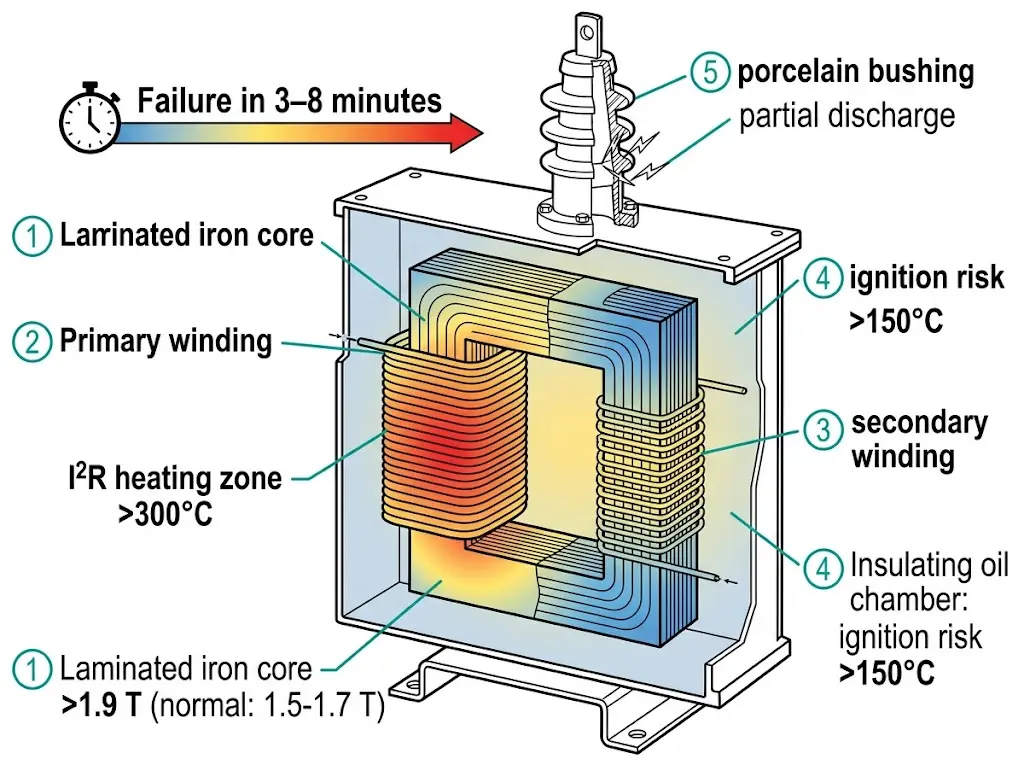
Damage Mode 1: Voltage Transformer Thermal Destruction
Electromagnetic voltage transformers suffer most frequently and most rapidly. During ferroresonance, core flux density can exceed 1.9–2.1 T (versus design limits of 1.5–1.7 T), driving the core into deep saturation. The resulting magnetizing current—10–50× normal values—generates extreme I²R losses in the primary winding.
Core temperatures can exceed 300°C within minutes. In our investigations, VT failures have occurred within 3–8 minutes of ferroresonance onset, with damage ranging from winding insulation failure to oil ignition in liquid-filled units.
Damage Mode 2: Insulation Breakdown from Sustained Overvoltage
Ferroresonance voltages of 2.5–4.0 p.u. persist for the duration of the resonant condition—potentially hours if undetected. While equipment may withstand 2.0 p.u. for short transients per IEC 60071-1 insulation coordination requirements, extended exposure at these levels initiates partial discharge activity and electrical treeing in solid insulation.
Epoxy-resin insulators, cable terminations, and bushing insulation are particularly vulnerable. The damage accumulates progressively, often manifesting as unexplained insulation failures weeks after the ferroresonance event.
Damage Mode 3: Surge Arrester Thermal Failure
Metal-oxide surge arresters are designed for brief energy absorption during lightning or switching surges. Ferroresonance forces continuous conduction through the arrester’s nonlinear resistance, dissipating energy far beyond thermal ratings.
Arrester failures range from thermal cracking to explosive fragmentation. We have documented arrester case temperatures exceeding 200°C during sustained ferroresonance events—well above the 60–80°C continuous operating limit specified by most manufacturers.
Damage Mode 4: Capacitor Bank Stress
Power factor correction capacitors connected to ferroresonant circuits experience current magnitudes 3–8× rated values. The capacitor dielectric undergoes accelerated aging, with failure modes including internal fuse operation, can bulging, and catastrophic case rupture.
Damage Mode 5: Circuit Breaker Contact Degradation
Repeated ferroresonance events during switching operations expose vacuum circuit breaker contacts to abnormal interruption duty. High-frequency current components in subharmonic or chaotic modes cause accelerated Cu-Cr contact erosion, potentially reducing interrupting capability over the equipment’s service life.
| Damage Mode | Equipment Affected | Primary Mechanism | Typical Time to Failure |
|---|---|---|---|
| Thermal destruction | Voltage transformers | Core saturation, I²R heating | 3–8 minutes |
| Insulation breakdown | Cables, bushings, insulators | Sustained overvoltage, PD | Hours to weeks |
| Arrester failure | Metal-oxide surge arresters | Continuous energy absorption | Minutes to hours |
| Capacitor stress | PF correction capacitors | Overcurrent thermal stress | Minutes to hours |
| Contact erosion | Vacuum circuit breakers | Abnormal interruption duty | Cumulative damage |
Transformer core design significantly influences ferroresonance susceptibility and damage severity. For specifications on core materials and magnetizing characteristics, see our power distribution transformer selection guide.
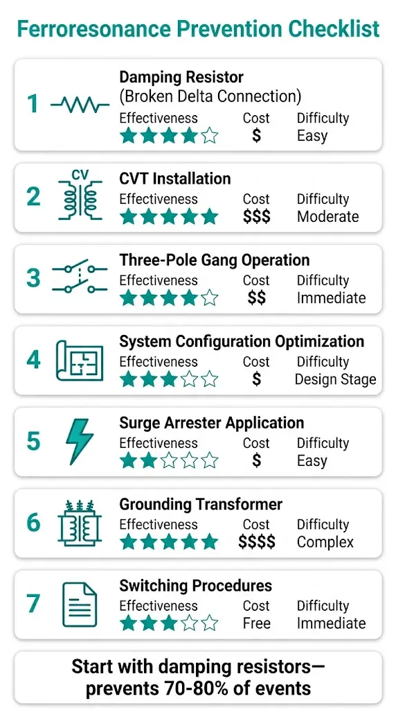
Preventing ferroresonance requires addressing the fundamental circuit conditions that enable resonance. The following checklist covers design-stage and retrofit solutions, ranked by effectiveness and implementation feasibility.
1. Install Damping Resistors on Voltage Transformer Secondaries
The most reliable prevention method for VT ferroresonance in ungrounded systems. A resistor (typically 50–150 Ω, rated for continuous duty) connected across the broken-delta secondary winding provides resistive damping that prevents resonance establishment. Size the resistor thermal rating to handle worst-case ferroresonance current for at least 10 seconds.
2. Specify Capacitive Voltage Transformers (CVTs) for New Installations
CVTs are inherently immune to ferroresonance because their primary energy storage element is capacitive rather than inductive. For new installations in ungrounded systems at 66 kV and above, CVT specification eliminates ferroresonance risk entirely. The higher initial cost is offset by eliminated damage risk.
3. Require Three-Pole Gang-Operated Switching Devices
Single-pole switching creates the unbalanced conditions that trigger ferroresonance. Specifying three-pole simultaneously operated circuit breakers and disconnectors ensures all phases switch together, eliminating the vulnerable single-phase energized configuration.
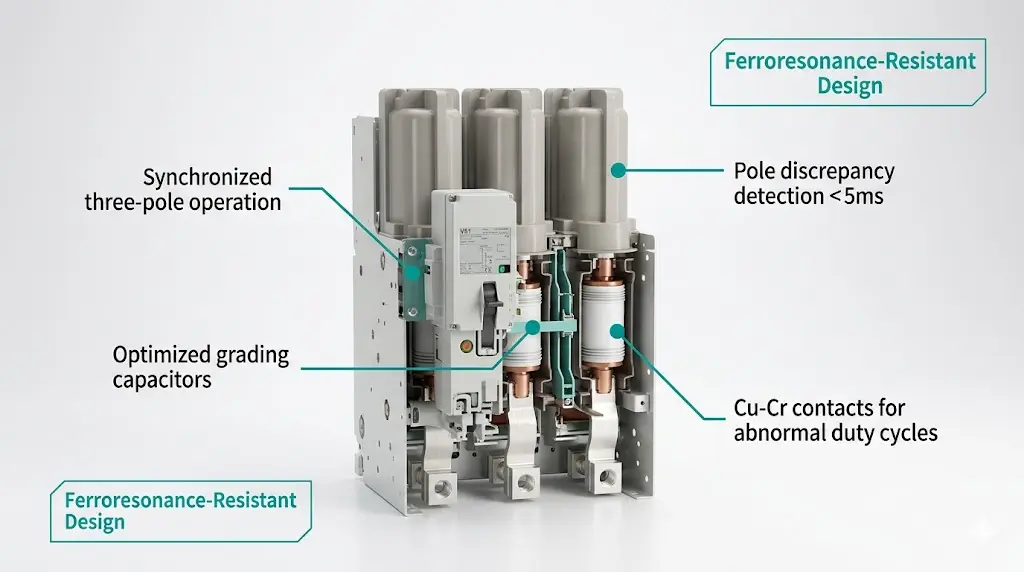
The VS1 indoor vacuum circuit breaker series features synchronized three-pole operation with pole discrepancy protection—an effective ferroresonance prevention measure for switchgear applications.
4. Evaluate Cable Capacitance During System Design
Calculate total capacitance-to-ground for each cable-transformer combination before finalizing designs. When the product of magnetizing inductance and cable capacitance falls within the ferroresonance-susceptible range, consider reducing cable length, selecting transformers with lower magnetizing inductance (accepting higher no-load losses), or adding permanent minimum load.
5. Install Ferroresonance-Rated Surge Arresters
Some surge arrester manufacturers offer units with enhanced energy absorption ratings specifically for ferroresonance-prone applications. These arresters clamp overvoltages while surviving extended conduction periods that would destroy standard units.
6. Add Grounding Transformers to Ungrounded Systems
A grounding transformer (zigzag or wye-delta configuration) provides a low-impedance neutral path that drains capacitive current, preventing ferroresonance establishment. This approach offers the most complete protection but carries the highest implementation cost and complexity.
7. Establish Switching Procedures for High-Risk Configurations
Where equipment modifications are impractical, operational procedures reduce risk: avoid switching unloaded transformers through long cable runs during low-load periods, close load-side switches first to establish damping before transformer energization, and document these requirements in formal switching orders.
| Prevention Method | Effectiveness | Relative Cost | Retrofit Feasibility |
|---|---|---|---|
| VT damping resistor | High | Low | Easy |
| CVT replacement | Very High | Medium-High | Moderate |
| Three-pole switching | High | Medium | Moderate |
| Cable capacitance analysis | Preventive | Low | Design stage |
| Ferroresonance-rated arresters | Moderate | Medium | Easy |
| Grounding transformer | Very High | High | Complex |
| Switching procedures | Moderate | None | Immediate |
[Expert Insight: Implementation Priorities]
- Start with damping resistors on existing VTs—this single modification prevents 70–80% of ferroresonance events in our experience
- For new projects, specify CVTs and three-pole switching from the design phase rather than retrofitting later
- Cable capacitance calculations cost nothing but prevent expensive surprises; request XLPE cable capacitance data from cable manufacturers (typically 0.2–0.4 μF/km for 10–35 kV ratings)
Several industry standards address ferroresonance directly or provide relevant insulation coordination and equipment testing requirements:
IEC Standards
IEEE Standards
CIGRE Technical Brochures
CIGRE Working Groups have published technical brochures on ferroresonance phenomena in transmission and distribution systems, providing detailed modeling approaches and case studies for protection engineers. [VERIFY STANDARD: CIGRE TB 569 ferroresonance scope—confirm availability]
These standards provide insulation withstand durations and thermal limits, but ferroresonance-specific testing is rarely mandated. Engineers must apply insulation coordination principles to evaluate equipment survival during ferroresonance events, recognizing that standards assume short-duration temporary overvoltages rather than the sustained conditions ferroresonance produces.
For foundational documents on transformer and surge arrester application, refer to IEEE Power & Energy Society Standards.
Ferroresonance prevention starts at equipment specification. XBRELE manufactures vacuum circuit breakers and contactors engineered for the demanding conditions of modern medium-voltage networks—including configurations where ferroresonance risk exists.
Our vacuum circuit breaker designs incorporate synchronized three-pole operation with mechanical interlocking and electrical pole discrepancy detection, preventing the single-phase switching conditions that trigger ferroresonance. Grading capacitor values are optimized to minimize contribution to system capacitance while maintaining proper voltage distribution across the interrupter gap.
Cu-Cr alloy contacts withstand the abnormal current interruption duty that occurs during ferroresonance events, maintaining interrupting capability throughout the equipment’s service life. For distribution transformer applications, our oil-immersed and dry-type transformer ranges are available with core designs optimized for specific magnetizing characteristics.
Request a technical consultation with our engineering team at XBRELE Vacuum Circuit Breaker Manufacturer to discuss ferroresonance mitigation strategies for your specific system configuration.
Q1: What system conditions make ferroresonance most likely?
A: Ferroresonance probability increases substantially in ungrounded or high-impedance grounded systems with cable-connected transformers, particularly when cable lengths exceed 150 m and transformer loading falls below 20% of rated capacity.
Q2: Can ferroresonance damage equipment that appears to operate normally afterward?
A: Yes—sustained overvoltages can initiate partial discharge activity in solid insulation without immediate failure, leading to unexplained insulation breakdowns weeks or months after the ferroresonance event.
Q3: How do I distinguish ferroresonance from other overvoltage conditions?
A: Ferroresonance produces characteristic subharmonic frequencies (16.7 Hz in 50 Hz systems) detectable through waveform analysis, accompanied by unusual transformer humming and phase-to-ground voltages exceeding 1.5 p.u. on phases that should be de-energized.
Q4: Are vacuum circuit breakers more likely to cause ferroresonance than other breaker types?
A: VCBs do not inherently cause ferroresonance, but their grading capacitors contribute to system capacitance. Properly designed three-pole gang operation actually reduces ferroresonance risk by preventing single-phase switching conditions.
Q5: What is the fastest way to stop an active ferroresonance event?
A: Connecting resistive load to the affected transformer collapses the resonant condition within seconds; alternatively, closing additional phases to restore balanced three-phase operation typically terminates oscillations.
Q6: Do modern digital relays detect ferroresonance automatically?
A: Some protection relays with waveform capture capability can detect ferroresonance through subharmonic content analysis and trigger alarms within 2–5 seconds, though this feature requires specific configuration and is not universally available.
Q7: Is ferroresonance covered under equipment warranty claims?
A: Most transformer and switchgear warranties exclude damage from ferroresonance because it results from system design or operating conditions rather than manufacturing defects—making prevention through proper specification essential.