Need Full Specifications?
Download our 2025 Product Catalog for detailed drawings and technical parameters of all switchgear components.
Get Catalog
Download our 2025 Product Catalog for detailed drawings and technical parameters of all switchgear components.
Get Catalog Download our 2025 Product Catalog for detailed drawings and technical parameters of all switchgear components.
Get Catalog
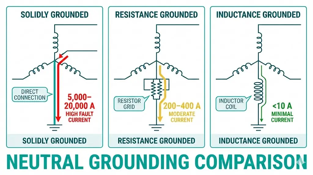
Neutral grounding method determines fault current magnitude, relay coordination requirements, and transient overvoltage behavior across your entire medium-voltage protection system. The three dominant approaches—solid grounding, neutral grounding resistor (NGR), and Petersen coil—create fundamentally different protection challenges and equipment specifications.
This comparison examines how each grounding method affects ground fault current paths, what changes in relay settings and switchgear ratings, and which applications favor each approach.
The neutral point in three-phase systems—typically the star point of transformers—can connect to earth through various impedance paths. This single connection governs what happens during single-line-to-ground (SLG) faults, which represent 70–80% of all distribution system faults.
When a phase-to-ground fault occurs, current flows from the faulted phase through fault impedance into earth, returning via the neutral grounding connection. The grounding impedance directly limits fault current magnitude.
[HTML-BLOCK-START]
The fault current magnitude If depends on system voltage and total impedance in the fault path. For a bolted fault on a 10 kV system with 400 A neutral grounding resistor (NGR), the ground fault current typically limits to 200–400 A, compared to 8,000–15,000 A in solidly grounded systems of equivalent MVA rating.[HTML-BLOCK-END]
Three parameters characterize any grounding system: fault current magnitude, transient overvoltage ratio, and ground fault detection sensitivity. These parameters trade off against each other—reducing fault current inherently increases overvoltage risk and complicates fault detection.
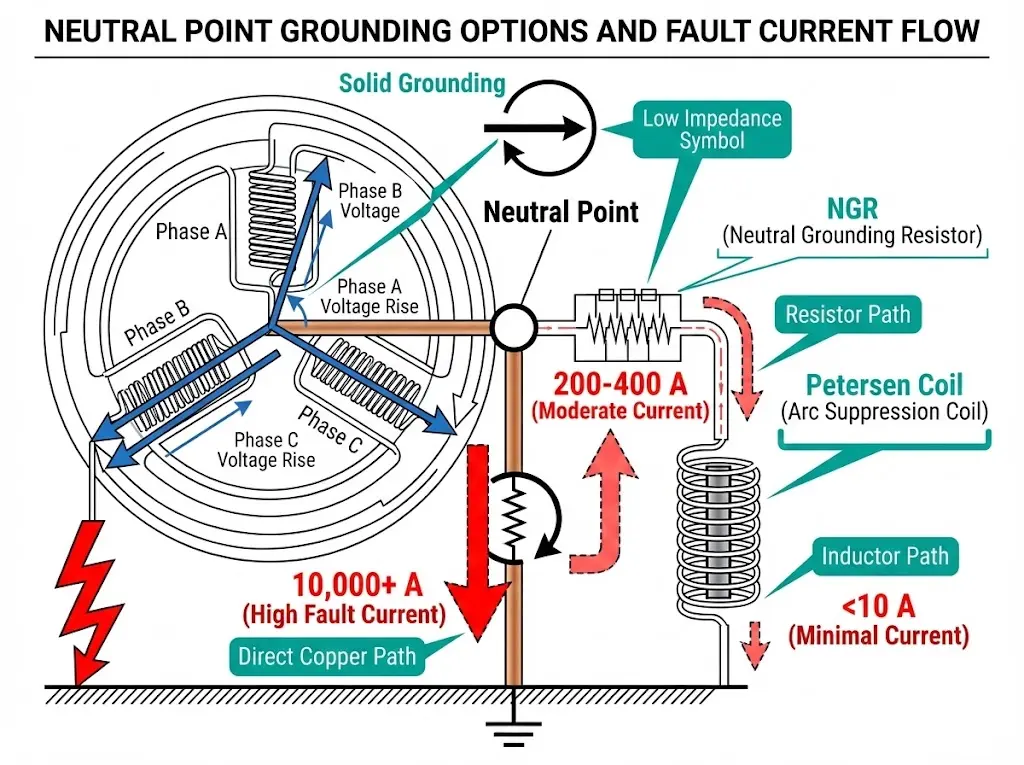
According to IEC 60364-4-44, overvoltage factor during ground faults reaches 1.73× line-to-neutral voltage in solidly grounded systems but may exceed 2.5× in resonant-grounded configurations during arcing faults.
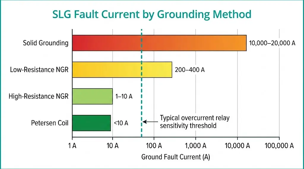
In solidly grounded systems, the transformer neutral connects directly to the earth electrode without intentional impedance. This creates a low-impedance fault current path, typically producing ground fault currents of 5,000–20,000 A depending on source impedance and fault location.
Fault Current Characteristics
Solid grounding permits maximum fault current flow—often comparable to or exceeding three-phase fault levels. On a 13.8 kV system with 500 MVA available fault duty, SLG faults routinely produce 8,000–15,000 A. This high magnitude ensures reliable operation of standard overcurrent relays without sensitivity concerns.
The fault clears within 3–6 cycles when instantaneous elements operate. Fast clearing limits equipment damage but generates severe arc flash hazard at the fault point.
Protection Scheme Requirements
Standard time-overcurrent coordination applies. Ground fault relays (50G/51G) set at 10–40% of phase pickup operate reliably with conventional CT ratios. Coordination studies follow familiar time-current curve methodology.
Advantages:
Limitations:
Utility distribution feeders at 4.16–34.5 kV predominantly use solid grounding where fast fault clearing takes priority over continuity.
[Expert Insight: Field Observations on Solid Grounding]
- In our assessments across 40+ industrial substations at 6–35 kV, solidly grounded systems consistently showed the fastest fault clearing but highest repair costs at fault locations
- Ground fault current magnitude often exceeded 120% of three-phase fault current at remote feeder locations due to zero-sequence impedance distribution
- Arc flash incident energy calculations per IEEE 1584 typically yield 8–25 cal/cm² at working distance on solidly grounded 13.8 kV systems
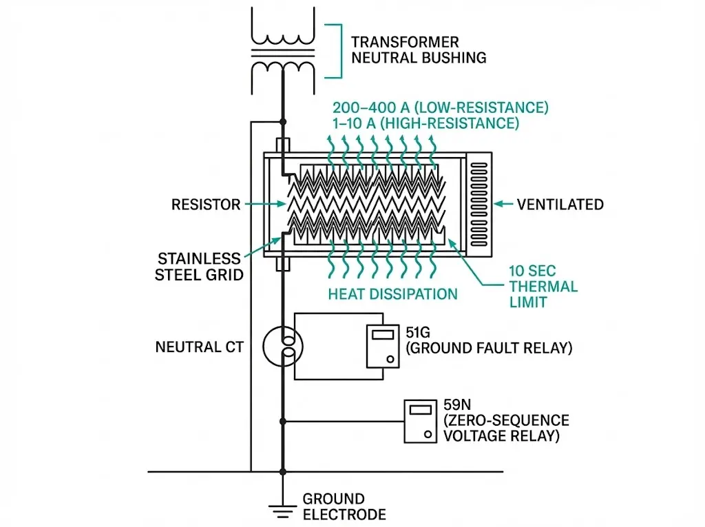
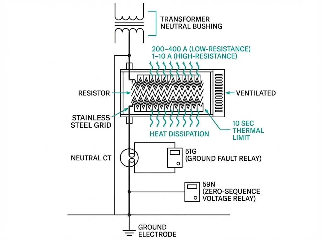
NGR systems insert calibrated resistance between the neutral and earth. This resistance limits fault current to predetermined levels while maintaining sufficient magnitude for protective relay operation.
Low-Resistance vs High-Resistance Grounding
Low-resistance grounding (LRG) limits fault current to 100–1,000 A, typically 200–400 A. Standard overcurrent relays operate reliably, but fault clearing must occur within 10 seconds to prevent resistor thermal damage. LRG suits industrial systems requiring definite fault clearing with reduced arc flash hazard.
High-resistance grounding (HRG) limits fault current to 1–10 A, sized to exceed system capacitive charging current by factor of 1–2×. This minimal current cannot operate standard overcurrent elements. HRG systems use zero-sequence voltage relays (59N) or specialized pulsing ground fault detection, often alarming rather than tripping on first fault.
Protection Scheme Adaptations
LRG systems require ground fault relays with pickup settings of 5–15% of NGR current limit. A 400 A NGR system might use 50G pickup at 20–40 A with definite-time coordination.
HRG systems fundamentally change protection philosophy. Rather than immediate tripping, the first ground fault produces an alarm while the system continues operating. Maintenance personnel locate the faulted feeder using pulsing detection or sequential feeder switching.
Advantages:
Limitations:
Industrial facilities, generator neutrals, and mining operations commonly specify NGR grounding for the balance between safety and operational flexibility.
Petersen coils (arc suppression coils) introduce inductance that resonates with system phase-to-earth capacitance. When properly tuned, the coil generates reactive current that cancels capacitive fault current, reducing residual current at the fault point to 5–10 A or less.
Resonant Grounding Principle
The coil inductance is tuned so inductive current approximately equals system capacitive charging current. During an SLG fault, these currents—180° out of phase—cancel at the fault point. The small residual resistive current cannot sustain an arc, enabling self-extinction of transient faults.
CIGRE Technical Brochure 283 documents that approximately 80% of transient ground faults self-extinguish on resonant-grounded systems without breaker operation.
Tuning Requirements
System capacitance changes as feeders switch in/out or cable sections are added. Modern automatically-tuned Petersen coils (plunger-core or tap-changing designs) adjust reactance continuously. Detuning within ±5% generally maintains effective arc suppression.
Protection Challenges
Resonant grounding intentionally minimizes fault current—creating detection difficulties. Zero-sequence voltage relays indicate fault presence but cannot identify the faulted feeder. Specialized directional or wattmetric relays measuring active power component are required for feeder selection.
Permanent faults (downed conductor, failed equipment) require eventual isolation. The system tolerates delays while operators locate the fault, but continued operation with a sustained ground fault stresses unfaulted phase insulation.
Advantages:
Limitations:
European utilities extensively use Petersen coils for rural overhead medium-voltage distribution where transient faults from vegetation and wildlife dominate.
[Expert Insight: Petersen Coil Field Experience]
- Automatic tuning systems require 2–5 seconds to compensate after system topology changes—protection engineers must account for this window in coordination studies
- Unfaulted phase voltage rises to line-to-line value (1.73×) during sustained ground faults, requiring equipment rated accordingly
- Cable systems present high capacitance requiring impractically large coils; resonant grounding suits overhead-dominant networks
| Parameter | Solid Grounding | NGR (Low-R / High-R) | Petersen Coil |
|---|---|---|---|
| SLG Fault Current | 5,000–20,000 A | 200–400 A / 1–10 A | <10 A residual |
| Fault Clearing | Immediate (3–6 cycles) | Required (<10 s) / Alarm | Often self-clearing |
| Relay Type | Standard overcurrent | Overcurrent / Sensitive GF | Directional, wattmetric |
| CT Requirements | Standard ratios | May need lower ratios | Sensitive zero-sequence |
| Transient Overvoltage | ≤1.4 pu | ≤1.7 pu / ≤2.0 pu | ≤2.5 pu |
| Arc Flash Severity | High | Reduced / Minimal | Minimal |
| Service Continuity | Trip required | Trip required / Alarm first | Ride-through possible |
| Complexity | Low | Moderate | High |
| Best Applications | Utility distribution | Industrial, generators | Rural overhead networks |
Grounding method directly affects vacuum circuit breaker ratings and associated switchgear components.
Circuit Breaker Interrupting Duty
Solidly grounded systems require breakers rated for full SLG fault current—often the governing case exceeding three-phase levels at certain locations. NGR systems reduce ground fault interrupting duty to the resistor limit; three-phase fault becomes the rating determinant. Petersen coil systems rarely require breaker operation for ground faults, though permanent fault clearing still needs adequate capacity.
CT and Relay Selection
Standard 600:5 or 1200:5 CT ratios work well for solidly grounded systems. NGR systems may require 100:5 or 200:5 ratios for adequate ground fault relay sensitivity. Resonant systems need core-balance CTs with high sensitivity (often 50:1 or 100:1) for directional element operation.
Surge Arrester Coordination
Solidly grounded systems use arresters rated at 80% of maximum system voltage. Resonant systems require 100% rated arresters—a 25% increase affecting both arrester selection and insulation coordination throughout the installation.
Understanding these implications affects indoor vs outdoor VCB selection based on environmental exposure and grounding-related transient stresses.
Selection depends on system characteristics and operational priorities:
Favor Solid Grounding When:
Favor NGR When:
Favor Petersen Coil When:
Document the grounding philosophy in protection coordination studies. Future system modifications must respect original assumptions or require comprehensive restudy.
Whether your system uses solid grounding demanding full fault duty, NGR configurations with controlled currents, or resonant grounding requiring specialized transient handling, XBRELE switchgear meets the technical requirements.
Our engineering team understands how grounding method affects breaker specification, CT selection, and protection coordination. Contact XBRELE vacuum circuit breaker manufacturer to discuss switchgear solutions matched to your system’s grounding philosophy.
Q: What neutral grounding method produces the lowest ground fault current?
A: Petersen coil (resonant grounding) produces the lowest fault current—typically under 10 A residual—because the tuned inductor cancels system capacitive current at the fault point, often enabling arc self-extinction without breaker operation.
Q: Can standard overcurrent relays detect faults on high-resistance grounded systems?
A: Standard overcurrent relays cannot reliably detect HRG faults because current limits to 1–10 A, well below typical pickup thresholds; these systems require zero-sequence voltage relays or pulsing ground fault detection methods.
Q: How does grounding method affect circuit breaker interrupting rating selection?
A: Solidly grounded systems require breakers rated for full SLG fault current (potentially exceeding three-phase levels), while NGR systems reduce ground fault duty to the resistor’s current limit, making three-phase fault the governing rating case.
Q: Why do resonant-grounded systems have higher transient overvoltages?
A: The high neutral impedance allows unfaulted phase voltages to rise toward line-to-line values during ground faults, potentially reaching 2.5 per unit during arcing conditions compared to 1.4 per unit on solidly grounded systems.
Q: Which industries typically specify neutral grounding resistors?
A: Industrial facilities, mining operations, and generator installations commonly use NGR grounding to balance arc flash reduction against fault detection requirements; petrochemical and pulp/paper plants often favor high-resistance grounding for process continuity.
Q: Does neutral grounding affect surge arrester selection?
A: Solidly grounded systems permit arresters rated at 80% of maximum system voltage, while resonant-grounded systems require 100%-rated arresters to withstand higher transient overvoltages during ground faults—a 25% increase in arrester voltage class.
External Reference: IEEE C62.92 series — Guide for the Application of Neutral Grounding in Electrical Utility Systems — IEEE Standards Association