Need Full Specifications?
Download our 2025 Product Catalog for detailed drawings and technical parameters of all switchgear components.
Get CatalogDownload our 2025 Product Catalog for detailed drawings and technical parameters of all switchgear components.
Get CatalogDownload our 2025 Product Catalog for detailed drawings and technical parameters of all switchgear components.
Get Catalog
The ground bus inside metal-enclosed switchgear serves as more than a passive conductor. It determines whether personnel survive ground faults, whether protection relays operate correctly during switching transients, and whether equipment passes type testing. Getting the design wrong creates hazards that remain hidden until a fault occurs.
This guide covers practical ground bus design for medium-voltage switchgear—from sizing calculations and bonding topology selection to EMI immunity and field verification testing.
A properly designed switchgear ground bus performs three simultaneous functions. Neglecting any one creates safety hazards or operational failures.
Fault Current Return Path. When phase-to-ground faults occur, current must return to the source transformer neutral. The ground bus provides this low-impedance path. Insufficient capacity extends fault clearing time because protective relays see reduced current magnitude. A 31.5 kA-rated assembly requires ground bus impedance low enough for relay pickup within the first few cycles.
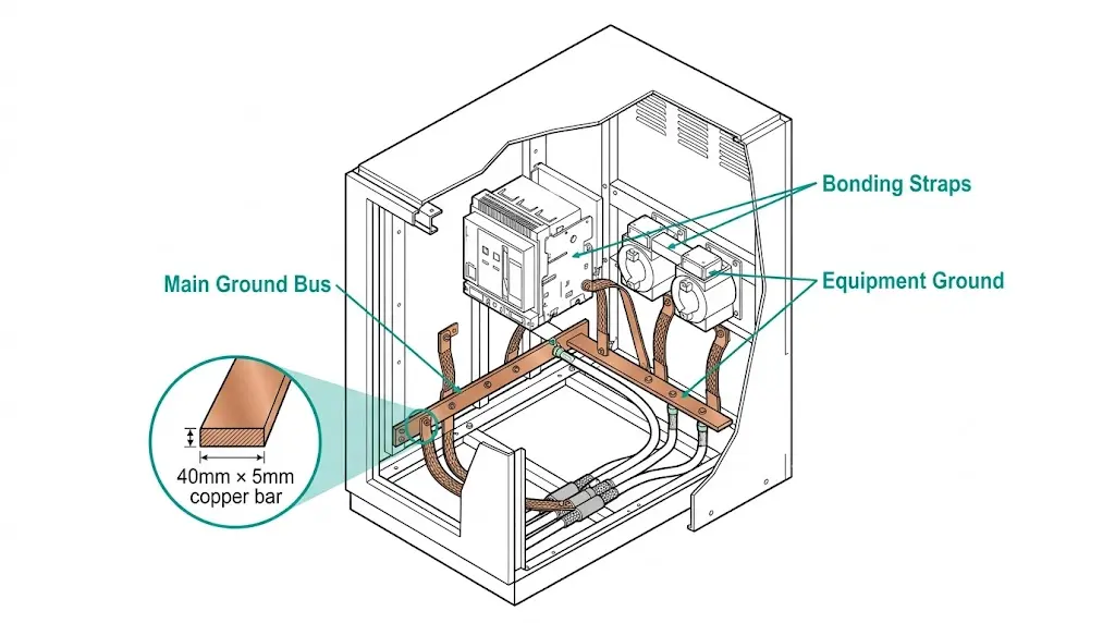
Equipotential Bonding. Every conductive surface a technician might touch—enclosure panels, door handles, operating mechanisms, instrument transformer cases—bonds to the ground bus. This ensures all surfaces rise to the same potential during a fault. Without proper bonding, one panel can sit at 500 V above another panel centimeters away. A technician bridging this gap receives the full voltage.
EMC Reference Plane. Modern switchgear contains microprocessor-based protection relays, digital meters, and communication interfaces. These electronics need a stable voltage reference. Vacuum circuit breakers generate particularly steep transients during current interruption—rise times under 200 nanoseconds. Without proper ground bus geometry, these transients couple into secondary circuits and cause relay misoperation.
The ground bus must satisfy all three functions simultaneously. A design optimized for fault current alone may fail EMC requirements.
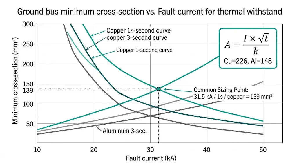
Ground bus sizing follows thermal withstand principles. The conductor must absorb fault energy without exceeding temperature limits that damage insulation or weaken mechanical joints.
The Adiabatic Equation
For short-duration faults, heat dissipation is negligible. The adiabatic formula governs minimum cross-section:
A = (I × √t) / k
Where: A = minimum cross-section (mm²), I = fault current (A), t = duration (s), k = material constant
Material constants for common conductors: copper k = 226, aluminum k = 148 (for 30°C initial to 250°C final temperature).
Practical Sizing Example
For 31.5 kA fault current with 1-second clearing using copper:
A = (31,500 × √1) / 226 = 139 mm²
Standard practice adds margin. Most 36 kV switchgear uses 40 mm × 5 mm copper bar (200 mm²).
| Parameter | Copper | Aluminum |
|---|---|---|
| Conductivity (% IACS) | 100 | 61 |
| k-factor (adiabatic) | 226 | 148 |
| Density (kg/m³) | 8,940 | 2,700 |
| Relative cost | 1.0 | 0.35–0.45 |
Aluminum ground buses require approximately 1.5× larger cross-section than copper for equivalent thermal performance.
[Expert Insight: Ground Bus Sizing]
- Field measurements across 40+ substations show actual fault durations typically run 60–150 ms with modern protection—well under the 1-second design basis
- Specify 1-second withstand for backup protection coordination; 3-second only where required by utility interconnection standards
- Joint temperature rise often exceeds mid-span temperature by 15–25°C due to contact resistance—size joints conservatively
Grounding topology selection depends on frequency content and physical dimensions. The wrong choice creates either circulating currents or inadequate high-frequency performance.
Single-Point Grounding
All bonds converge at one location on the ground bus. This prevents circulating ground currents at power frequency (50/60 Hz). Apply single-point grounding when:
Multi-Point Grounding
Multiple bonds connect enclosure sections to the ground bus at several locations. This approach provides lower impedance at high frequencies and better EMC performance. Modern switchgear assemblies with integrated protection relays typically require multi-point bonding.
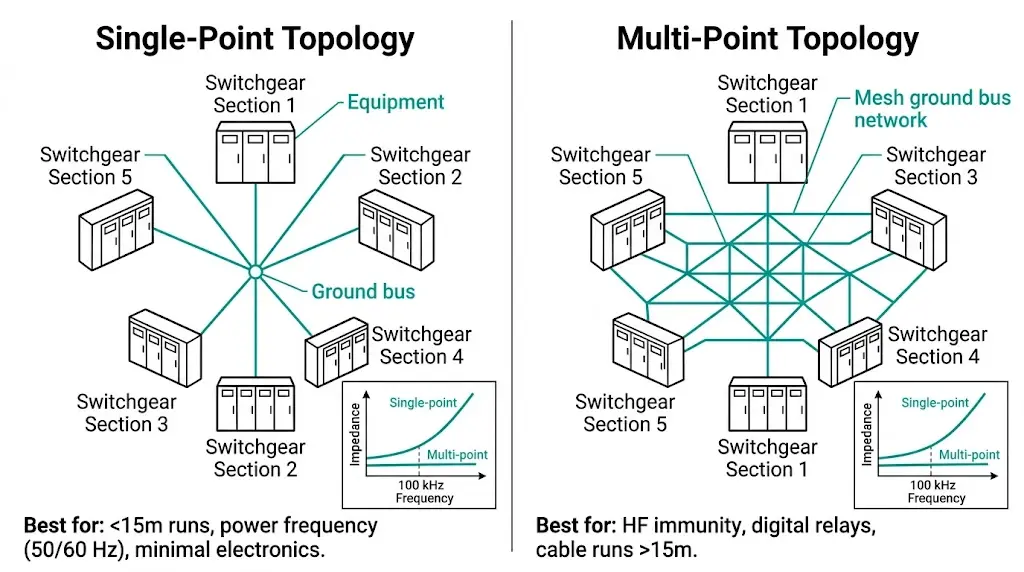
The Frequency Threshold
Transition occurs when conductor length approaches 1/20 of the wavelength. For switching transients with 1 MHz content:
λ = c/f = 3×10⁸ / 10⁶ = 300 m
At 1/20 wavelength (15 m), multi-point grounding becomes necessary.
| Application | Recommended Topology | Rationale |
|---|---|---|
| Legacy electromechanical relays | Single-point | Avoids 50/60 Hz circulating currents |
| Microprocessor protection relays | Multi-point | Provides HF reference plane |
| Capacitor bank switching | Multi-point | High transient frequency content |
| Cable connections > 15 m | Multi-point | Exceeds wavelength threshold |
Hybrid Approach
Most modern installations use multi-point bonding for enclosure panels with single-point grounding for instrument transformer secondary circuits. This combination addresses both power frequency and EMC requirements.
When fault current flows through the ground bus, enclosure potential rises above true earth. Touch voltage—the potential difference a person experiences between what they touch and where they stand—must remain within survivable limits.
IEC 61936-1 Permissible Limits
| Fault Clearing Time | Maximum Touch Voltage |
|---|---|
| ≤ 0.1 s | 700 V |
| 0.2 s | 430 V |
| 0.5 s | 220 V |
| 1.0 s | 110 V |
| > 1.0 s | 80 V |
These values assume dry conditions and account for body impedance per IEC 60479-1.
Design Calculation
Touch voltage depends on fault current and bonding impedance:
V_touch = I_f × Z_bond
For 31.5 kA fault current with 1-second clearing (110 V limit):
Z_bond ≤ 110 / 31,500 = 3.5 mΩ
This extremely low impedance requires short, direct ground connections with large cross-section conductors and multiple parallel paths.
Equipotential Zone Design
Inside the switchgear room, a meshed ground grid beneath the floor connects to the switchgear ground bus. Personnel standing on this grid remain at nearly the same potential as equipment they touch. Minimum bonding jumper cross-section: 35 mm² copper connecting all accessible metallic surfaces.
Switching operations generate electromagnetic interference that threatens control circuit integrity. Ground bus geometry determines whether transients cause protection relay malfunction.
Transient Sources in Switchgear
| Source | Rise Time | Frequency Content |
|---|---|---|
| Vacuum interrupter chopping | 50–200 ns | 5–20 MHz |
| Disconnector operation | 5–50 ns | 20–200 MHz |
| Vacuum contactor switching | 100–500 ns | 2–10 MHz |
| Capacitor bank energization | 1–10 μs | 100 kHz–1 MHz |
Low-Inductance Geometry
At high frequencies, inductance dominates over resistance. Design principles:
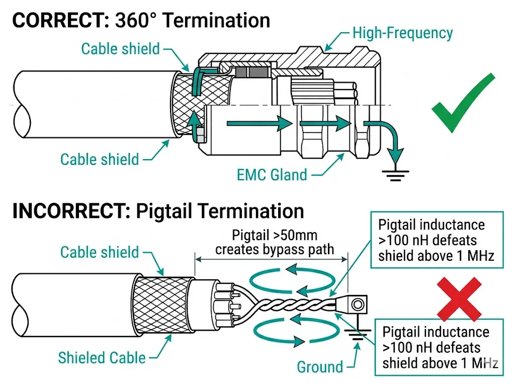
Cable Shield Termination
Shielded control cables require proper termination:
CT/PT Secondary Grounding
Instrument transformer secondary circuits require single-point grounding to prevent circulating currents from distorting measurements. Ground at the relay panel or transformer terminal—never both locations.
[Expert Insight: EMC Field Experience]
- In coastal petrochemical installations, we’ve measured relay misoperations reduced by 85% after converting from pigtail to 360° shield termination
- Fiber optic communication links between switchgear bays eliminate ground loop problems entirely for protection signaling
- CT secondary cables routed parallel to ground bus (within 50 mm) show 40% lower transient coupling than perpendicular routing
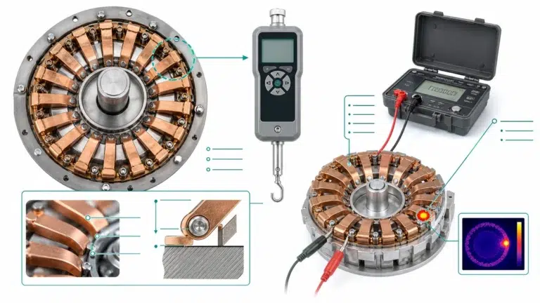
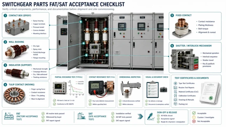
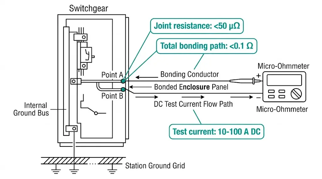
Ground bus performance depends entirely on joint quality. Hardware selection and installation practices determine whether the system maintains low impedance over its 30-year service life.
Connection Types Compared
| Method | Contact Resistance | Maintenance | Cost |
|---|---|---|---|
| Bolted (bare Cu) | 10–50 μΩ | Periodic re-torque | Low |
| Bolted (tin-plated) | 5–20 μΩ | Minimal | Medium |
| Exothermic weld | < 5 μΩ | None | High |
| Compression connector | 10–30 μΩ | Periodic inspection | Medium |
Bimetallic Joint Treatment
Copper-to-aluminum connections require special attention:
Without these precautions, galvanic corrosion increases joint resistance 10–100× within 5–7 years.
Torque Specifications
| Bolt Size | Steel (8.8) | Stainless |
|---|---|---|
| M8 | 20–25 N·m | 15–18 N·m |
| M10 | 40–50 N·m | 30–35 N·m |
| M12 | 70–85 N·m | 50–60 N·m |
Belleville washers maintain contact pressure through thermal cycling. Earthing switches designed for switchgear applications incorporate optimized contact systems that maintain low resistance over thousands of operations.
Environmental Protection
Verification testing confirms ground bus performance under fault conditions and during normal operation. IEC 62271-200 specifies type test requirements; field commissioning adds practical verification.
Type Tests (Design Verification)
Short-Circuit Withstand Test
The ground bus must survive rated short-time withstand current without:
Procedure:
Routine Tests (Production)
Every switchgear assembly undergoes:
Field Commissioning Tests
Ground Grid Continuity
After installation, measure:
Touch Voltage Verification
For critical installations:
Ground bus integrity depends on components engineered for the demanding environment inside metal-enclosed switchgear. XBRELE manufactures switchgear parts with attention to grounding requirements:
Every component undergoes testing to verify grounding system compatibility. Engineers specifying XBRELE components receive technical documentation detailing bonding requirements and installation practices.
For switchgear projects requiring reliable grounding solutions, contact XBRELE’s engineering team to discuss your application requirements.
Q: What cross-section should I specify for a 25 kA ground bus?
A: For 1-second fault duration using copper, calculate approximately 110 mm² minimum; standard practice rounds up to 150–200 mm² (such as 40×5 mm bar) to provide margin for joint heating and future system upgrades.
Q: How do I decide between single-point and multi-point grounding?
A: Choose multi-point grounding when switchgear contains microprocessor-based relays or when any cable run exceeds 15 meters; single-point applies only to simple installations with electromechanical protection and short internal distances.
Q: What touch voltage is acceptable for outdoor switchgear?
A: For typical 0.5-second fault clearing, IEC 61936-1 permits up to 220 V; wet or high-traffic areas may require design to 80 V continuous limit depending on local regulations and risk assessment.
Q: How often should ground bus joints be re-torqued?
A: Indoor installations typically require torque verification every 3–5 years; outdoor or high-vibration environments warrant annual checks, with contact resistance measurement every 5 years to detect degradation.
Q: Can I use braided straps instead of solid copper bonding jumpers?
A: Braided straps work well for connections requiring flexibility (such as door bonds) but exhibit higher impedance at high frequencies; use solid conductors for main ground bus runs and EMC-critical connections.
Q: What contact resistance indicates a failing ground bus joint?
A: Individual bolted joints should measure below 50 μΩ when new; resistance exceeding 100 μΩ or showing more than 50% increase from baseline indicates degradation requiring maintenance.
Q: Do I need separate grounding for digital relays and power circuits?
A: No—modern practice bonds all grounds to a common bus but uses separate conductor runs from sensitive electronics to the ground bus, maintaining physical separation from power fault current paths while achieving common reference potential.
Authority reference: For standard definitions and test context, see IEC 62271-200 publication page.