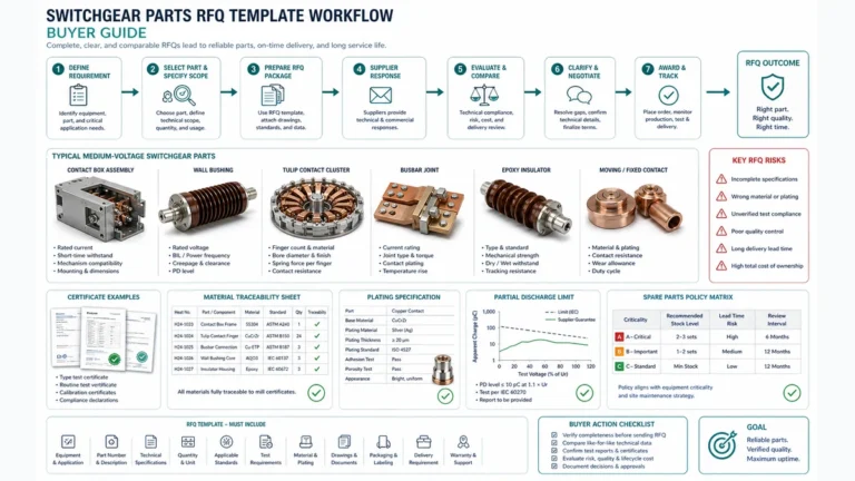
Need Full Specifications?
Download our 2025 Product Catalog for detailed drawings and technical parameters of all switchgear components.
Get CatalogDownload our 2025 Product Catalog for detailed drawings and technical parameters of all switchgear components.
Get CatalogDownload our 2025 Product Catalog for detailed drawings and technical parameters of all switchgear components.
Get Catalog
In medium voltage (MV) electrical distribution systems, protective relays serve as the critical first line of defense against electrical faults, equipment damage, and personnel hazards. Understanding how these relays interlock and communicate through trip logic maps is fundamental to designing, commissioning, and maintaining reliable power systems.
Over my 18 years of experience commissioning MV switchgear across petrochemical plants, data centers, and utility substations, I’ve witnessed firsthand how poorly coordinated relay schemes can cascade into catastrophic failures. Conversely, properly designed trip logic maps have saved millions of dollars in equipment and, more importantly, prevented injuries.
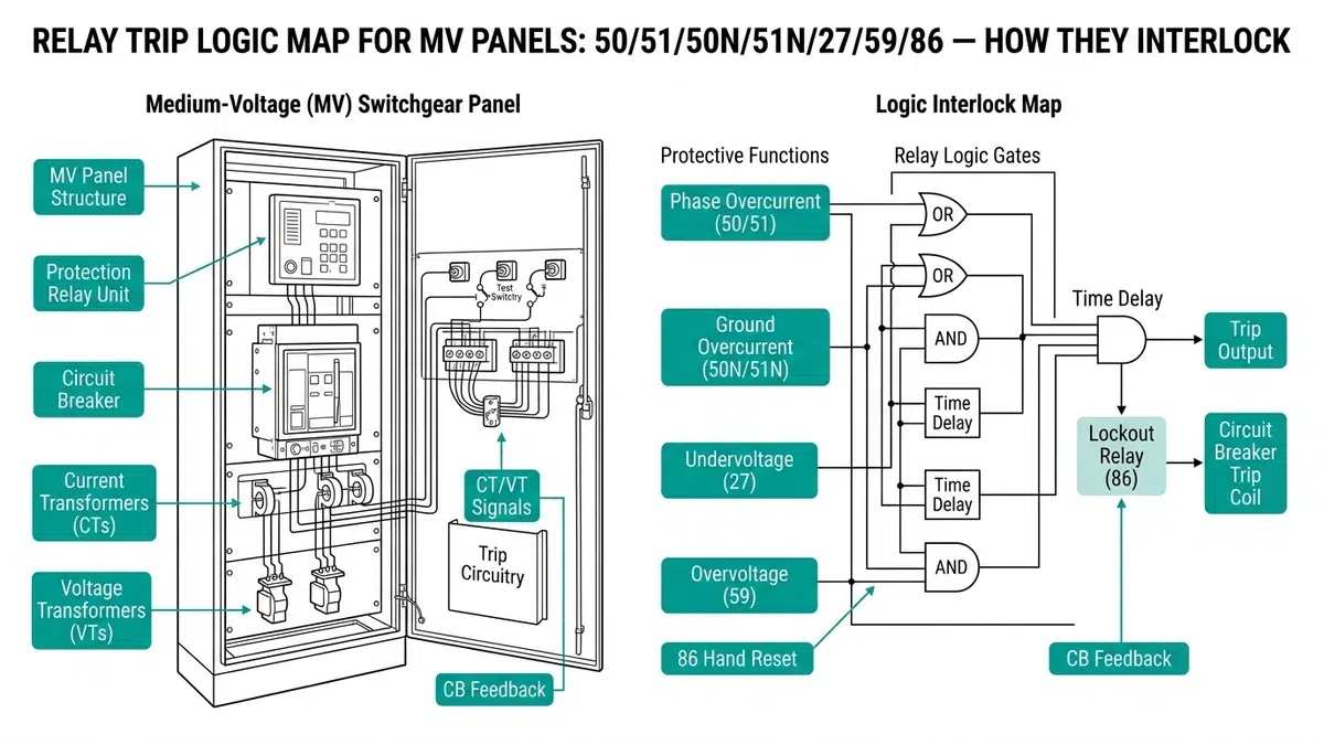
This article provides an in-depth examination of the most common protective relay functions—ANSI device numbers 50, 51, 50N, 51N, 27, 59, and 86—and explains how they interlock within MV panel architectures. Whether you’re a protection engineer designing new systems or a field technician troubleshooting existing installations, this guide will serve as a practical reference for understanding relay trip logic coordination.
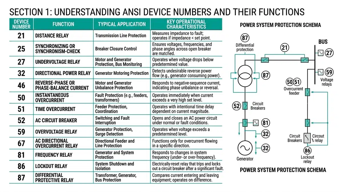
Before diving into interlock schemes, we must establish a clear understanding of each relay function. The ANSI/IEEE C37.2 standard defines device numbers that have become the universal language of protection engineering.
Device 50 (Instantaneous Overcurrent) operates without intentional time delay when current exceeds a predetermined threshold. Typical pickup settings range from 6 to 10 times the full-load current for transformer protection and 1.5 to 2 times for motor applications. The instantaneous element provides high-speed fault clearing for close-in faults where damage potential is greatest.
Device 51 (Time Overcurrent) introduces an inverse time-current characteristic, allowing downstream devices to clear faults before upstream relays operate. This coordination is achieved through standardized curves (IEC extremely inverse, very inverse, standard inverse, or IEEE moderately inverse, very inverse, extremely inverse).
Device 50N (Instantaneous Ground Overcurrent) detects ground faults through residual current measurement. In solidly grounded systems, pickup settings typically range from 10-20% of phase CT rating. For resistance-grounded systems, settings must coordinate with the maximum let-through current of the neutral grounding resistor.
Device 51N (Time Overcurrent Ground) provides time-coordinated ground fault protection, essential in systems where selective coordination between multiple ground fault devices is required.
Device 27 (Undervoltage) protects against voltage sags and loss of supply, typically set between 80-90% of nominal voltage with time delays of 1-10 seconds depending on application. This function is critical for motor protection and preventing automatic restart under degraded conditions.
Device 59 (Overvoltage) guards against sustained overvoltage conditions that can damage insulation and connected equipment. Settings typically range from 110-120% of nominal voltage.
Device 86 (Lockout Relay) is an electrically operated, hand-reset device that maintains circuit breakers in their tripped position until an operator manually acknowledges the fault condition. This function is fundamental to ensuring faults are investigated before re-energization.
| ANSI device | Protection role | Typical trip path | Commissioning check |
|---|---|---|---|
| 50 / 51 | Instantaneous and time overcurrent protection | Relay output to breaker trip coil or 86 lockout relay | Secondary current injection at pickup and time-dial settings |
| 50N / 51N | Ground fault protection using residual or neutral current | Ground-fault trip routed to feeder breaker and alarm circuit | CT polarity, residual summation, and NGR current setting verification |
| 27 / 59 | Undervoltage and overvoltage supervision | Trip, alarm, or load-shedding logic depending on application | Voltage injection, delay timing, and blocking logic validation |
| 86 | Manual-reset lockout after critical faults | Blocks closing circuit until operator reset | Trip latch, target indication, close-block contact, and reset test |
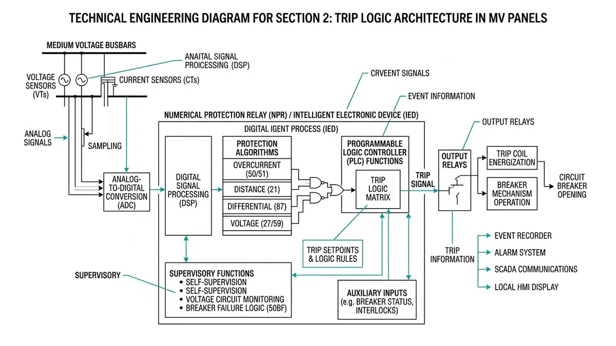
The trip logic map defines how protective relay outputs connect to circuit breaker trip coils, lockout relays, and auxiliary systems. Modern MV panels employ three primary trip architectures:
In simple applications, individual relay trip contacts wire directly to the circuit breaker trip coil. While economical, this approach lacks the benefits of consolidated fault indication and requires separate auxiliary contacts for each relay to block automatic reclosing.
More sophisticated schemes route all protective relay outputs through an 86 lockout relay. This configuration offers several advantages:
Modern numerical relays implement trip logic internally through programmable logic gates. The relay’s output contacts can be configured to represent individual protection elements or combined trip functions.
The interaction between protective functions follows established principles that ensure both dependability (operating when required) and security (not operating falsely).
The 50/51 and 50N/51N functions must coordinate in time and magnitude. Consider a typical configuration:
For a 2000A MV feeder with 2000:5 CTs:
– 51 pickup: 1.2 × FLA = 2400A (6A secondary)
– 51 time dial: 0.5 on very inverse curve
– 50 pickup: 8 × FLA = 16,000A (40A secondary)
– 51N pickup: 0.5A secondary (200A primary, 10% CT rating)
– 51N time dial: 0.3 on very inverse curve
– 50N pickup: 2A secondary (800A primary)
The ground fault elements are set more sensitively because ground faults typically involve lower magnitudes than phase faults, yet they’re equally dangerous.
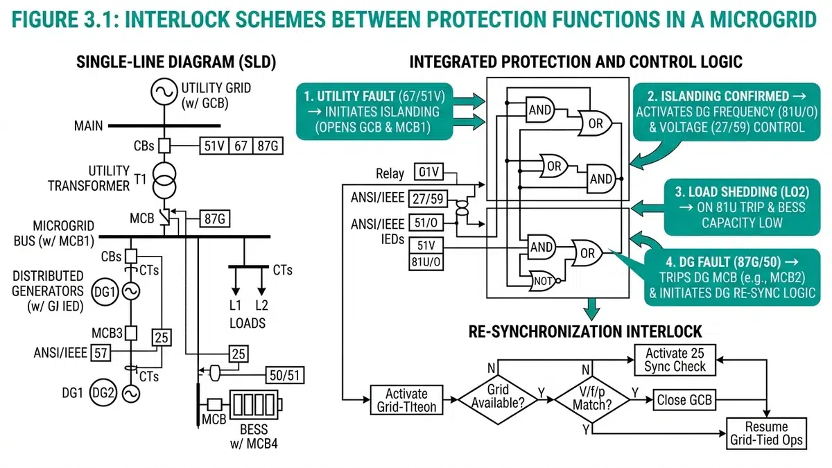
Undervoltage (27) and overvoltage (59) protection often interlock with overcurrent functions to enhance scheme security:
Voltage Restraint Overcurrent (51V) reduces pickup threshold as voltage decreases, improving sensitivity to remote faults where voltage depression is significant but current increase is modest.
Voltage-Controlled Overcurrent enables the overcurrent element only when voltage drops below a threshold, providing backup protection for generator applications.
The 86 device receives inputs from all protection functions and provides outputs to:
– Primary trip coil (52a path)
– Backup trip coil (if equipped)
– Close circuit blocking contact (52Y)
– SCADA/DCS alarm
– Local annunciation
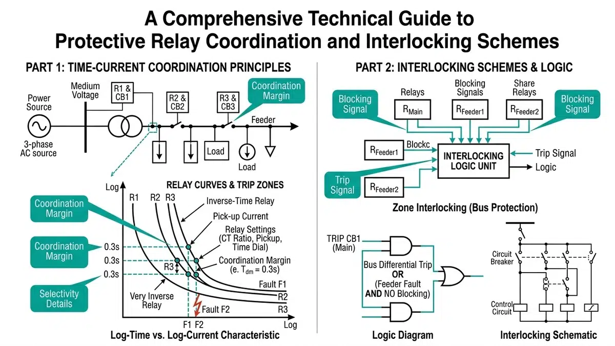
Achieving selective coordination requires systematic analysis of time-current characteristics across the protection system.
The minimum coordination time interval (CTI) between upstream and downstream devices must account for:
– Breaker clearing time (typically 3-5 cycles for MV breakers)
– Relay overtravel (2-4 cycles for electromechanical, negligible for numerical)
– Safety margin (5-10 cycles)
Industry practice establishes CTI of 0.2-0.4 seconds between successive devices. The formula is:
CTI = Breaker Time + Relay Overtravel + Safety Margin
For modern numerical relay and vacuum breaker combinations:
CTI = 0.08s + 0.00s + 0.12s = 0.20s minimum
The 50 function presents coordination challenges because it operates without intentional time delay. Two approaches ensure selectivity:
Zone Selective Interlocking (ZSI): Downstream relays send blocking signals to upstream devices when they detect faults in their zone. The upstream relay delays operation for a short interval (typically 50-100ms) unless it receives no blocking signal, indicating a bus fault.
Instantaneous Pickup Coordination: Set the upstream 50 element above the maximum let-through current of the downstream device, ensuring only downstream faults cause upstream 50 operation.
A manufacturing facility’s 13.8kV feeder supplies a 3000kVA transformer. The protection scheme includes:
Primary Protection:
– 51: Pickup 125A, Very Inverse, TD 3.0
– 50: Pickup 4000A (2× transformer inrush)
– 51N: Pickup 15A, Very Inverse, TD 2.0
– 50N: Pickup 200A
Interlocking:
All elements trip through 86T (transformer lockout), which trips the 13.8kV feeder breaker and blocks the 480V secondary main. The 27 element (set at 85%, 2.0s delay) trips the 480V secondary main independently to prevent motor stalling during voltage sags.
A 34.5kV bus tie breaker protects against bus faults and provides backup protection:
Zone Selective Interlock Implementation:
– Feeder relays send ZSI blocking signals to bus tie relay
– Bus tie 51: Pickup 2000A, Very Inverse, TD 5.0
– Bus tie 50: Pickup 8000A, delayed 100ms without ZSI block
– Bus tie 50N: Pickup 400A, delayed 100ms without ZSI block
When a feeder fault occurs, the feeder relay sends a blocking signal while operating to clear the fault. If no blocking signal exists (bus fault), the bus tie trips instantaneously.
Proper commissioning validates that the trip logic map functions as designed.
From field experience, the most frequent problems include:
Contemporary protection schemes leverage numerical relay capabilities for enhanced functionality.
Modern relays allow creation of custom logic equations:
TRIP = (50 OR 51 OR 50N OR 51N OR 27 OR 59) AND NOT BLOCK
Where BLOCK might be a maintenance mode input or external permissive.
IEC 61850 GOOSE messaging enables high-speed interlocking without hardwired connections. Typical applications include:
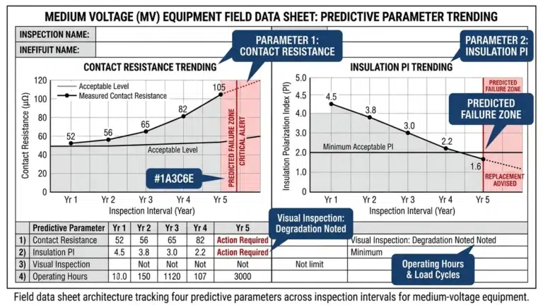
Numerical relays capture oscillography and event records crucial for post-fault analysis. This data validates trip logic operation and identifies any coordination failures.
Relay systems require ongoing maintenance to ensure reliability throughout their service life.
Based on NFPA 70B and industry practice:
Maintain accurate records including:
– Original relay settings and coordination study
– As-built wiring diagrams
– Test results and trending data
– Firmware revision history for numerical relays
– Event record analysis for any operations
The 50 (instantaneous) and 51 (time overcurrent) functions serve complementary roles. The 51 element provides coordinated protection with time delays that allow downstream devices to clear faults first, maintaining selectivity. The 50 element provides high-speed protection for severe faults close to the relay location where damage potential is greatest and coordination with downstream devices isn’t possible or necessary. Together, they provide complete coverage: selective operation for remote faults and fast operation for close-in faults.
Use an 86 lockout relay when any of these conditions apply: (1) multiple protection devices protect the same equipment and consolidated fault indication is desired, (2) automatic reclosing must be blocked until fault investigation is complete, (3) the protection scheme requires a clear operator interface for fault acknowledgment, or (4) regulatory requirements mandate hand-reset functionality. Direct tripping is appropriate for simple, non-critical applications where automatic reclosing is acceptable and installation cost is a primary concern.
The appropriate CTI depends on the relay and breaker technologies employed. For modern numerical relays with vacuum breakers, 0.20-0.25 seconds is typically adequate. When electromechanical relays are involved, use 0.30-0.40 seconds to account for relay overtravel. For series coordination studies involving both technologies, use the larger value. Always verify CTI adequacy at multiple current levels, particularly at the maximum fault current where curves may converge.
No. ZSI enhances time coordination but doesn’t replace it. The scheme must maintain selectivity even if ZSI communication fails. Consider ZSI as a performance enhancement that allows faster upstream relay operation for bus faults while maintaining backup protection capability. Always design the base coordination scheme to function correctly without ZSI, then add ZSI to improve performance for specific fault locations.
In resistance-grounded systems, maximum ground fault current is limited by the neutral grounding resistor (NGR). Set the 51N pickup at 10-25% of the NGR current rating to ensure sensitivity to high-resistance faults while maintaining security against unbalanced load conditions. The 50N pickup should be set at 50-80% of maximum ground fault current. Time coordination is less critical than in solidly grounded systems because all ground faults produce similar current magnitudes regardless of location, but selective 51N coordination is still required if multiple devices are in series.
Common causes include: (1) time delay settings that are too short to ride through normal voltage transients during motor starting or load switching, (2) pickup settings that are too high relative to normal voltage variations, (3) inadequate VT burden calculations causing voltage measurement errors, (4) lack of coordination with upstream voltage regulators or tap changers, and (5) improper VT secondary wiring that introduces voltage drop. Typical solutions involve time delays of 2-5 seconds and pickup settings of 80-85% nominal voltage, though specific applications may require different values.
Numerical relays can implement logical lockout functions internally, maintaining a latched trip state that requires manual reset through the relay HMI or communication interface. However, external 86 devices remain preferred for critical applications because they provide: (1) hardwired, fail-safe blocking of the breaker close circuit, (2) visible target flags that don’t require relay interrogation, (3) a definitive manual reset action that forces operator acknowledgment, and (4) independence from relay power supply availability. Many facilities use both: internal logical lockout for first-line protection with external 86 devices for backup and regulatory compliance.
Effective relay trip logic design in MV panels requires systematic integration of multiple protection functions into a coordinated scheme. The fundamental principles include:
The investment in properly designed and commissioned relay trip logic pays dividends through improved equipment protection, reduced downtime, and enhanced personnel safety. As protection technology continues to evolve with digital communication and advanced analytics, these fundamental principles of coordination and interlocking remain essential to reliable power system operation.
For additional technical resources on protective relaying, the IEEE Power System Relaying and Control Committee (PSRCC) maintains comprehensive standards and tutorials at IEEE PES PSRCC.