Need Full Specifications?
Download our 2025 Product Catalog for detailed drawings and technical parameters of all switchgear components.
Get CatalogDownload our 2025 Product Catalog for detailed drawings and technical parameters of all switchgear components.
Get CatalogDownload our 2025 Product Catalog for detailed drawings and technical parameters of all switchgear components.
Get Catalog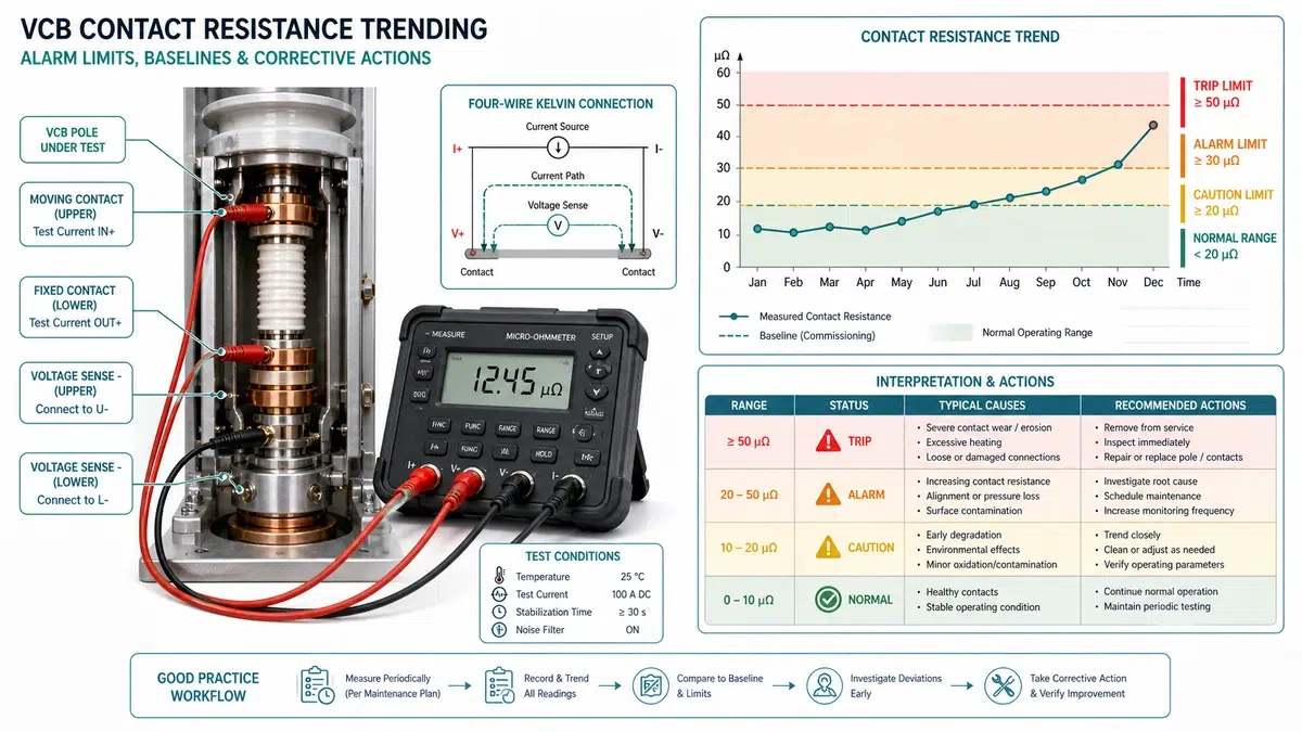
Vacuum circuit breaker contact resistance is one of the few measurable parameters that gives advance warning of a failure mode that is otherwise invisible until the breaker either fails to interrupt or overheats under load. This guide covers how alarm limits are set, how to measure and trend resistance accurately, how to diagnose the root cause when a limit is breached, and how to select corrective actions and replacement parts. The structure follows the workflow a maintenance engineer actually uses in the field: confirm the measurement, interpret the trend, diagnose the cause, act, and procure.
Use this table as the first filter when a resistance reading exceeds the alarm limit. It maps the most common symptom patterns to a likely root cause and the next action before opening the breaker.
| Symptom | First Test | Likely Root Cause | Next Action |
|---|---|---|---|
| All three phases elevated uniformly, gradual onset | Repeat test with verified leads and fresh probe contact | Oxidation film or dried lubricant on contact surfaces | Perform 3-5 no-load operations; re-measure; inspect if no improvement |
| Single phase elevated, other two normal | Verify with second instrument; check adjacent breaker | Vacuum interrupter damage or localized contamination | Measure contact travel; inspect terminal hardware for arc marks |
| Step increase on one or two phases after known fault | Confirm measurement; review switching log | Arc pitting or micro-welding from fault energy | Remove from service; inspect interrupter; replace if travel is within spec but resistance remains high |
| Resistance elevated but drops after several operations | Wipe test: 5 close-open cycles, re-measure | Surface contamination or oxide film | Schedule contact inspection; clean at next outage |
| Phase-to-phase spread > 30% of lowest reading | Check all three poles with same instrument and leads | Partial loss of contact pressure on one pole | Measure contact wipe on divergent phase; check spring force |
| Reading lower than baseline by > 20% | Recheck probe seating; verify test current | Measurement error or probe contact issue | Retest with verified setup; investigate if anomaly persists |
| Resistance stable but above OEM maximum at commissioning | Cross-check against factory test certificate | Incorrect baseline or installation issue | Investigate before energizing; do not accept as a new baseline |
| Instrument / Source | Specification or Use | Risk if Misapplied |
|---|---|---|
| Micro-ohmmeter (DLRO / DLRO10) | 100 A DC injection; four-wire Kelvin connection | Low-current models (< 10 A) give unstable readings on oxidized contacts |
| High-current micro-ohmmeter | 200-600 A DC; large generator or bus-tie breakers | Thermal heating at high current can shift results on distribution-class VCBs |
| Multimeter (resistance mode) | Continuity check only; < 1 mA test current | Never acceptable for contact resistance trending; cannot resolve micro-ohm range |
| Dial gauge / contact travel gauge | Measures contact wipe and erosion against OEM tolerance | Incorrect reference point gives false pass on worn contacts |
| Spring balance gauge | Verifies contact pressure force against manufacturer spec | Skipping this step misses spring fatigue as a resistance cause |
| Hi-pot tester | Vacuum integrity test after interrupter replacement; typically 36 kV / 1 min for 12 kV class | Wrong voltage class or duration invalidates the test |
| Thermal imaging camera | Supplementary in-service indicator only | Cannot substitute for a controlled injection test against alarm limits |
| OEM manual / OEM instruction manual | Absolute maximum resistance value; test current specification; contact travel tolerances | Using a generic value instead of the nameplate-specific limit creates false pass or false alarm |
| Project specification | Site-specific acceptance source for alarm limits, maintenance interval, insulation test level, and reporting format | Overriding the project specification with a generic number can create a contractual non-conformance |
| IEC 62271-100 | Type test and routine test methods for AC circuit breakers | Misapplying type-test limits to field maintenance decisions |
| IEEE C37.09 | Test procedure for AC high-voltage circuit breakers | Mixing test method standards invalidates cross-comparison |
| Site maintenance procedure | Site-specific alarm limits and trending intervals | Overriding site limits with generic values without engineering authorization |
| Factory acceptance test report | Contact resistance at defined test current; post-installation acceptance band | Accepting a replacement interrupter without this document prevents valid baseline establishment |
For external method context, compare the site procedure with the public IEEE C37.09 standards page and then apply the exact OEM manual and project specification for the supplied breaker.
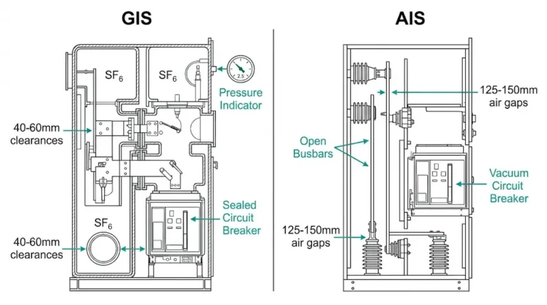
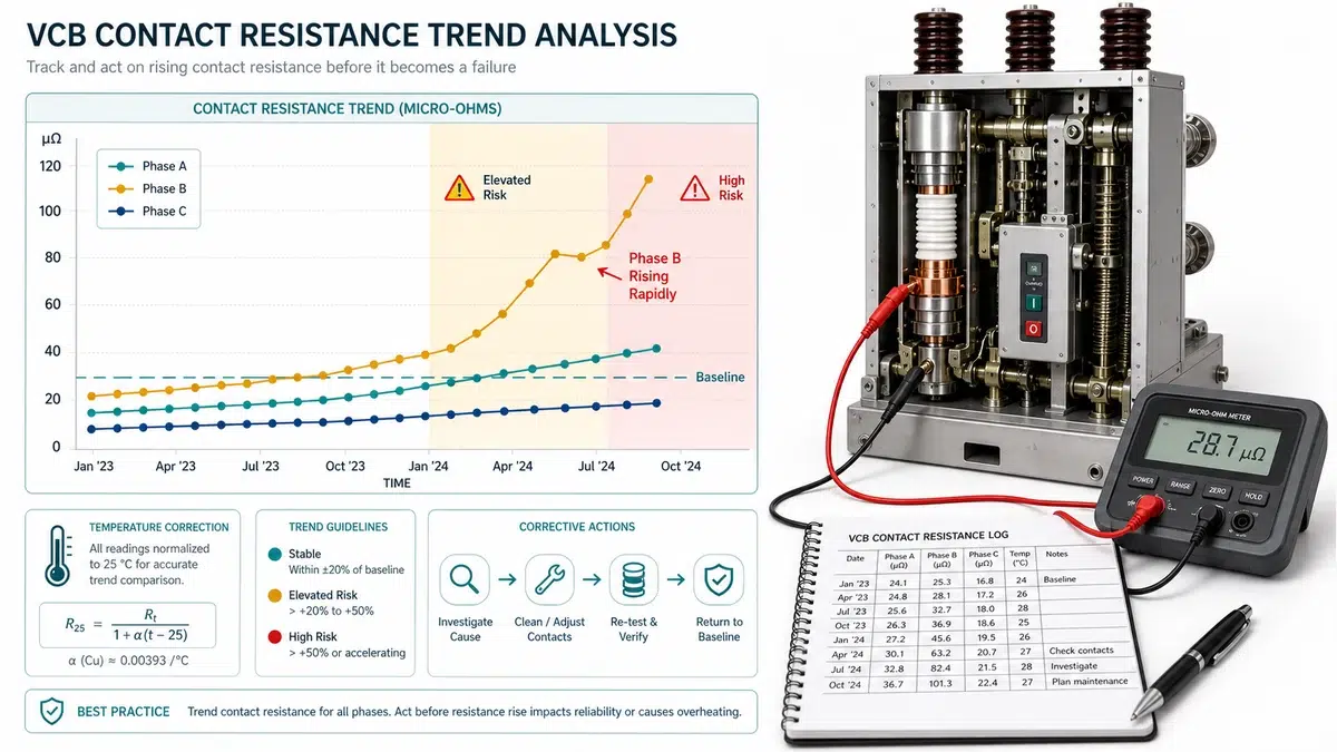
In a healthy vacuum circuit breaker, closed-contact resistance typically falls between 20 and 100 micro-ohm for medium-voltage interrupters, depending on contact diameter, material, and rated current. This value rises as contacts erode through switching arcs, accumulate oxide films, lose spring pressure from fatigue, or suffer mechanical misalignment.
| Term | Definition | Typical Derivation |
|---|---|---|
| Factory baseline | Resistance measured at commissioning or after full contact replacement | Manufacturer test certificate or first DLRO measurement on site |
| Site baseline | First measured value after installation under operating conditions | Recorded during commissioning DLRO sweep |
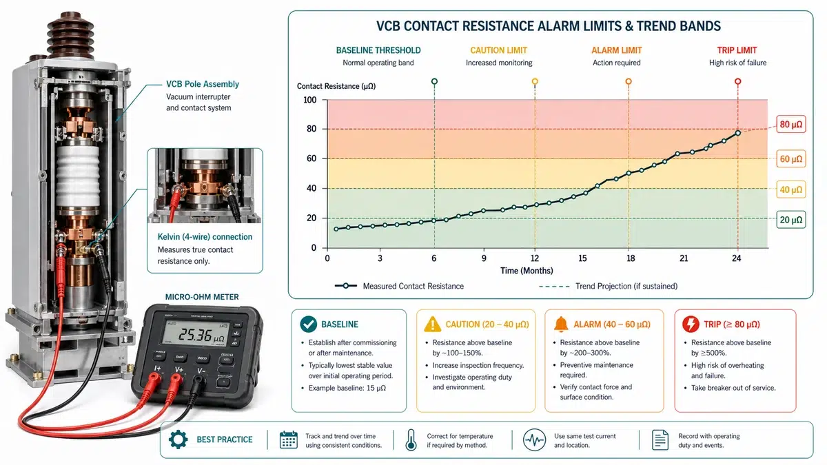
| Caution threshold | Resistance reaching 150-200% of the site baseline | Engineering judgment; triggers increased monitoring frequency |
| Alarm limit | Resistance reaching 200-300% of the site baseline, or an absolute manufacturer limit | Manufacturer specification, IEEE C37.09, or IEC 62271-100 guidance |
| Rejection limit | Absolute value beyond which the breaker must be withdrawn from service | Often 300 micro-ohm for medium-voltage VCBs; confirm against nameplate rating |
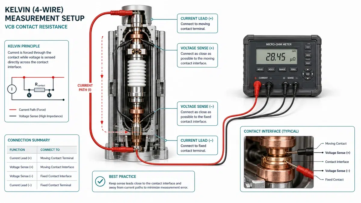
Accurate measurement is the foundation of any meaningful trending program. The breaker must be racked out or isolated from the bus, in the closed position, with stored energy in the operating mechanism released or secured before connecting any instrument.
| Condition | Interpretation | Action |
|---|---|---|
| Reading <= OEM max and within +/- 20% of baseline | Acceptable | Record; continue normal inspection interval |
| Exceeds OEM max by <= 50% OR 20-50% above baseline | Advisory threshold | Flag for re-test within 90 days; inspect interrupter hours and mechanical wear |
| Exceeds OEM max by > 50% OR > 50% above baseline | Alarm threshold | Take out of service; investigate before return to service |
| Phase-to-phase spread > 30% of lowest reading | Asymmetric degradation | Treat the highest-reading phase as alarm regardless of absolute value |
| Reading lower than baseline by > 20% | Possible measurement error | Retest with verified probe contact; investigate if anomaly persists |
A single resistance reading tells you where a contact is today. A trend tells you whether it will still be acceptable at the next scheduled outage.
| Contact Condition | Typical Baseline Range (micro-ohm) | When This Range Is Expected |
|---|---|---|
| New, factory-assembled | 20-60 | First commissioning, no prior operations |
| Refurbished / re-gapped | 40-90 | After contact replacement or interrupter swap |
| Aged but serviceable | 60-120 | Mid-life unit with normal operation count |
| Approaching end-of-life | 120-200 | High-duty or near mechanical endurance limit |
| Rate of Increase | Interpretation | Recommended Action |
|---|---|---|
| < 10% of baseline per interval | Normal aging | Continue scheduled trending |
| 10-25% of baseline per interval | Moderate degradation | Shorten trend interval; inspect at next outage |
| 25-50% of baseline per interval | Accelerated degradation | Flag for priority maintenance; investigate cause |
| > 50% of baseline per interval | Abnormal – possible mechanical or contact damage | Take out of service for inspection at earliest opportunity |
| Error | Why It Corrupts the Trend | Corrective Practice |
|---|---|---|
| Mixing test currents (e.g., 100 A vs. 200 A) | Higher injection current produces lower apparent resistance; trend appears to improve | Standardize on one current level for all measurements on a given asset |
| Testing immediately after operations | Contact heating suppresses resistance temporarily | Allow 30-minute thermal soak after operations before testing |
| Not recording operation count | Rate-of-change calculation becomes impossible | Log cumulative operations at every measurement |
| Using a new instrument mid-trend without calibration cross-check | Instrument offset creates a step change in the trend | Perform parallel measurements with old and new instruments at transition |
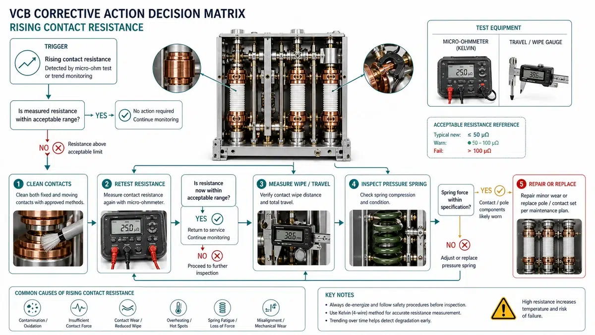
When a reading crosses the alarm threshold, the measurement alone does not identify the fault. The same elevated resistance value can result from contact surface oxidation, mechanical misalignment, contaminated interrupter vacuum, worn contact material, or a failed test lead connection.
| Question | Yes – Go To | No – Continue |
|---|---|---|
| Has the breaker operated >= rated mechanical or electrical life cycles? | Contact wear path | Next question |
| Was the last maintenance > 5 years or > manufacturer interval? | Oxidation / contamination path | Next question |
| Did resistance rise suddenly after a known fault interruption or close-onto-fault event? | Post-fault arc damage path | Mechanism / alignment path |
Field example: during a 12 kV water-treatment feeder service call, Phase B measured 142 micro-ohm against a 58 micro-ohm commissioning baseline, while Phase A measured 61 micro-ohm and Phase C measured 64 micro-ohm. The maintenance team first repeated the DLRO test with fresh Kelvin lead contact, then checked timing and travel. Because the service example showed one-phase divergence rather than a uniform three-phase rise, the corrective action focused on contact pressure and pole-unit inspection, not a generic cleaning procedure.
When trending data or a discrete measurement pushes contact resistance above the alarm limit, the corrective path depends on the magnitude of the deviation, the rate at which it developed, and the field conditions that produced it.
| Measured Resistance | Rate of Change | Field Condition | Recommended Action |
|---|---|---|---|
| Baseline to 1.5x baseline | Stable, < 5 micro-ohm change over 2 cycles | Normal temperature, low humidity | Document; continue trending at normal interval |
| 1.5x to 2x baseline | Gradual (< 10 micro-ohm per cycle) | Elevated humidity, moderate dust | Clean contact fingers and arcing chamber exterior; re-test; adjust trending interval to 6 months |
| 1.5x to 2x baseline | Accelerating (> 10 micro-ohm per cycle) | Corrosive or coastal atmosphere | Contact surface inspection; silver-layer thickness check; re-lubricate mechanism if contact pressure confirmed low |
| 2x to 3x baseline | Any rate | Any | Mandatory inspection; measure contact erosion; perform mechanism timing test; do not return to service without written engineering disposition |
| > 3x baseline | Any rate | Any | Remove from service; contact or breaker replacement required before re-energization |
| Any value showing sudden step increase >= 20 micro-ohm | Not applicable | Post-fault or high switching duty | Immediate removal; internal inspection for contact welding, pitting, or arc residue |
When alarm limits are breached and trending confirms a degradation trajectory, the procurement decision carries consequences for installation timeline, warranty validity, and long-term resistance stability that are not recoverable after the purchase order is placed.
Before finalizing any purchase, request from the supplier: the contact resistance acceptance band at the current used in your plant’s test procedure; the minimum contact gap dimension defining end-of-life; confirmation of the vacuum integrity test method used before shipment with pass criterion stated; and a traceability record linking the interrupter serial number to its factory test data. Suppliers who cannot provide all four documents before the purchase is finalized represent a qualification gap.
If the replacement decision also changes the breaker rating or product family, review the XBRELE vacuum circuit breaker range and the VCB ratings guide before accepting the quotation. For incoming inspection, connect the purchase order to the VCB FAT/SAT acceptance checklist and keep the micro-ohm contact resistance testing guide as the supporting measurement reference. If the issue is still at quotation stage, include alarm-limit and baseline-record requirements in the VCB RFQ checklist.
There is no single universal value. Most medium-voltage VCBs have a manufacturer-specified maximum in the range of 100-300 micro-ohm, but the operationally meaningful alarm limit is set as a multiplier of the site commissioning baseline, typically 2x for a caution threshold and 3x (or the manufacturer’s absolute maximum, whichever is lower) for the alarm limit that triggers corrective action.
The baseline schedule is at commissioning, at 12 months or 500 operations, and at 24 months or 1,000 operations, then every 1-3 years depending on switching duty. High switching duty applications (greater than 1,000 operations per year, capacitor bank switching, motor feeder service) warrant quarterly trending.
No. A standard multimeter in resistance mode injects less than 1 mA of test current, which is insufficient to resolve the micro-ohm range relevant to VCB contacts.
Single-phase divergence is a stronger diagnostic signal than uniform three-phase elevation. Common causes include partial loss of contact pressure on one pole from spring or mechanism fault, localized contamination or moisture ingress into one interrupter, or vacuum interrupter damage from a fault-clearing event on that phase.
Operating above the alarm limit increases I2R heating at the contact interface, which accelerates further degradation in a self-reinforcing cycle. At sufficient resistance levels, the contact interface can reach temperatures that cause contact welding on the next close operation or reduce the breaker’s interrupting capacity under fault conditions.
Yes, but the new baseline will not necessarily match the original commissioning value. A refurbished or replacement interrupter typically produces a baseline in the 40-90 micro-ohm range rather than the 20-60 micro-ohm range of a new factory-assembled unit.