Benötigen Sie die vollständigen Spezifikationen?
Laden Sie unseren Produktkatalog 2025 herunter, um detaillierte Zeichnungen und technische Parameter aller Schaltanlagenkomponenten zu erhalten.
Katalog anfordernLaden Sie unseren Produktkatalog 2025 herunter, um detaillierte Zeichnungen und technische Parameter aller Schaltanlagenkomponenten zu erhalten.
Katalog anfordernLaden Sie unseren Produktkatalog 2025 herunter, um detaillierte Zeichnungen und technische Parameter aller Schaltanlagenkomponenten zu erhalten.
Katalog anfordern
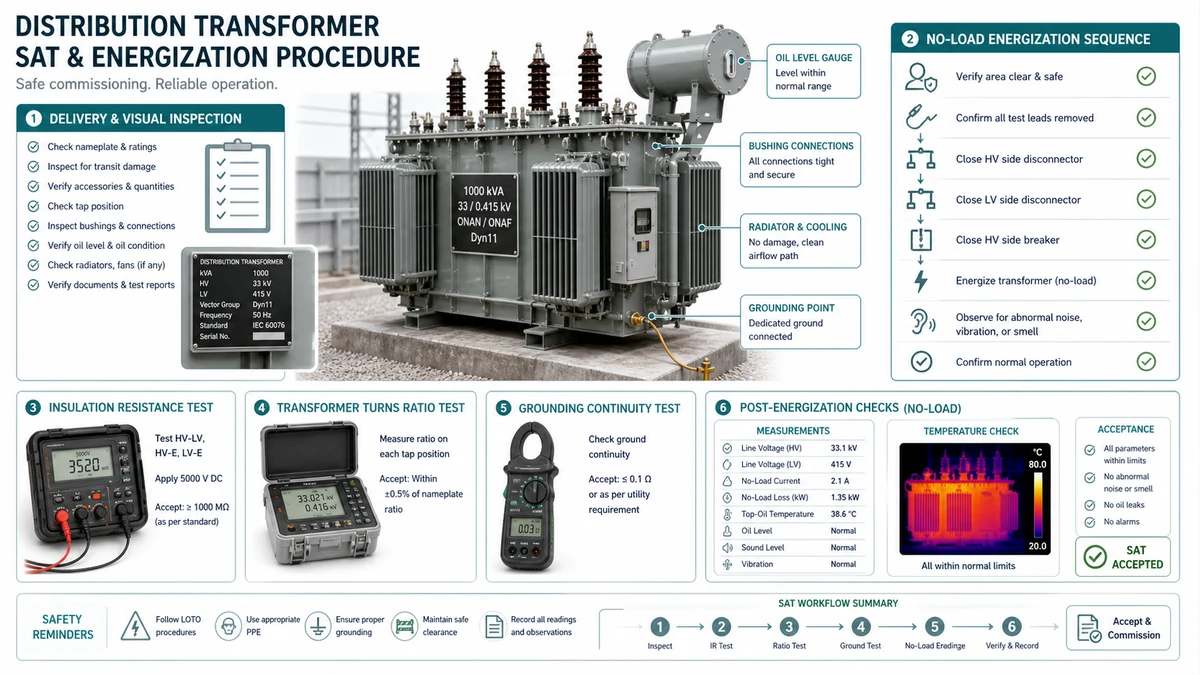
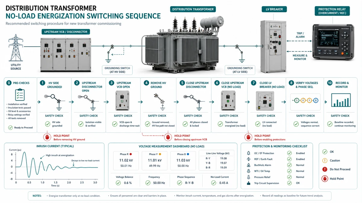
A distribution transformer SAT energization procedure defines the structured sequence of site acceptance tests and switching steps required before a new transformer is placed into service. When followed correctly, it confirms that the unit survived transport, was installed within specification, and will not fail under initial energization transients.
This guide covers the full workflow from delivery inspection through post-energization acceptance, with field-executable checklists, acceptance tables, and a troubleshooting framework. It applies to single-phase and three-phase distribution transformers rated from 25 kVA up to approximately 2,500 kVA on primary voltages through 36 kV. Units with on-load tap changers (OLTC) require additional commissioning steps beyond those shown here.
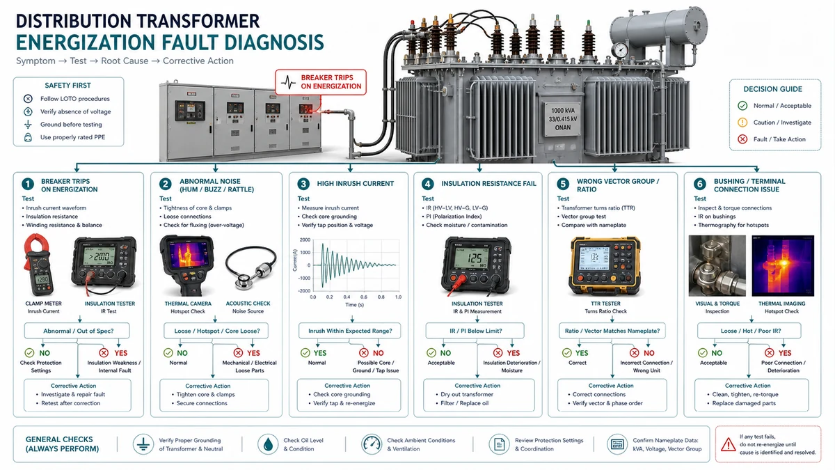
Before diving into the full procedure, field supervisors can use this table to triage any anomaly that appears during or immediately after energization.
| Symptom | Erster Test | Wahrscheinliche Grundursache | Nächste Aktion |
|---|---|---|---|
| Differential relay trips on energization | Check CT polarity and relay vector-group setting | CT wiring reversal or wrong vector-group compensation | De-energize; reverse CT leads or correct relay setting; re-test by injection before re-energizing |
| Inrush does not decay within 2 seconds | Measure excitation current vs. factory baseline | Partial core saturation or incipient turn fault | De-energize; compare excitation current to factory report; perform DGA |
| LV phase voltage imbalance >2% at no load | Re-measure TTR on all three phases | Winding connection error or open-delta fault | De-energize; re-verify terminal connections and turns ratio |
| Audible banging or cracking at energization | Listen for location; perform DGA if oil-filled | Loose core laminations or internal arcing | De-energize immediately; DGA before any further attempt |
| Oil temperature rising rapidly at no load | Check cooling system operation; verify no-load loss value | Cooling failure or shorted turns | De-energize; check cooler fans/pumps; compare no-load loss to factory figure |
| Buchholz alarm within 30 minutes of energization | Collect relay gas sample; Dräger tube analysis | Incipient thermal fault generating gas | De-energize; analyze gas composition; do not re-energize until fault source identified |
| IR reading below 500 MOhm (HV-to-ground) | Re-measure corrected to 20 deg C; check PI | Moisture ingress in winding or bushing turret | Defer energization; oil sampling for water content; dry-out if confirmed |
| Winding resistance phase imbalance >2% | Re-check terminal torque; re-measure with stabilized current | Loose connection or tap-changer contact resistance | Re-torque terminals; inspect tap-changer contacts; re-test |
| Instrument oder Quelle | Purpose in SAT | Acceptance Reference |
|---|---|---|
| Insulation resistance tester (5,000 V DC for HV; 1,000 V DC for LV) | IR and polarization index measurement | IEEE Std 43; IEC 60076-1 |
| Low-resistance ohmmeter / micro-ohmmeter | Winding resistance and contact resistance | OEM factory test report; IEC 60076-1 |
| Transformer turns ratio (TTR) bridge or automated ratio tester | Turns ratio on all tap positions | IEEE C57.12.90; project specification |
| True-RMS multimeter | Voltage, auxiliary supply, and trip coil continuity | OEM manual; project wiring diagrams |
| Clamp meter (true-RMS) | Load current, CT secondary output, neutral current | Coordination study; project specification |
| Power quality analyzer | THD, power factor, harmonic content | IEC 61000-series; project specification |
| Wärmebildkamera | Bushing, lug, and tank surface hotspots | NETA MTS; OEM manual |
| Secondary current injection test set | Relay pickup, slope, and inrush blocking verification | Relay setting file; protection engineer’s specification |
| Durchgangswiderstandsprüfer | Tap-changer contact resistance | OEM tap-changer manual |
| Dissolved gas analysis (DGA) kit or laboratory service | Pre- and post-energization gas baseline | IEC 60599; CIGRE guidelines |
| Karl Fischer moisture titrator | Oil moisture content | IEC 60814; OEM specification |
| OEM factory test certificate | Baseline winding resistance, TTR, losses | OEM signed test report |
| Project specification and single-line diagram | Voltage class, vector group, protection settings | Project engineer of record |
For IEEE standards on transformer testing methodology, the IEEE C57 transformer standards collection is the primary external authority reference for acceptance criteria used throughout this procedure.
Damage or incorrect configuration discovered after a transformer has been installed costs significantly more to correct than problems caught at delivery. Structure the inspection into two phases: a pre-arrival document review and a systematic physical assessment at the point of receipt.
| Dokument | What to Confirm | Rote Flagge |
|---|---|---|
| Purchase order vs. nameplate data sheet | kVA rating, primary/secondary voltage, vector group, tap range | Any mismatch triggers a hold |
| Werksprüfbericht (Routineprüfungen) | No-load loss, load loss, impedance, TTR within +-0.5% of spec | Missing report or values outside tolerance |
| Shipping and packing list | Quantity of bushings, tap-changer handle, gaskets, oil drum if shipped dry | Missing accessories discovered after energization |
| Insulation class and altitude rating | Verify rated for site altitude; derate applies above 1,000 m | Standard rating applied to high-altitude site |
Shock and tilt indicators: Read the impact recorder before offloading. A triggered indicator mandates a hold and engineering review before energization.
Structural and sealing integrity: Inspect tank and radiators for dents or weld separation, examine bushings for chips or cracks, and check conservator breather silica gel color-pink or white indicates moisture ingress during transit.
| Zustand | Disposition |
|---|---|
| No triggered indicators, no structural damage, oil clear, pressure positive | Accept; proceed to installation and SAT |
| Triggered indicator, no visible damage | Hold; engineering review required before SAT |
| Cracked bushing(s) | Reject or repair; do not energize |
| Zero or negative nitrogen pressure | Hold; moisture testing required before oil fill |
| Oil milky or black | Hold; laboratory analysis required before energization |
| Nameplate does not match purchase order | Hold; manufacturer clarification required before installation |
| Minor cosmetic damage (surface scratches, paint chips to primer) | Accept with documented note; repair before outdoor service exposure |
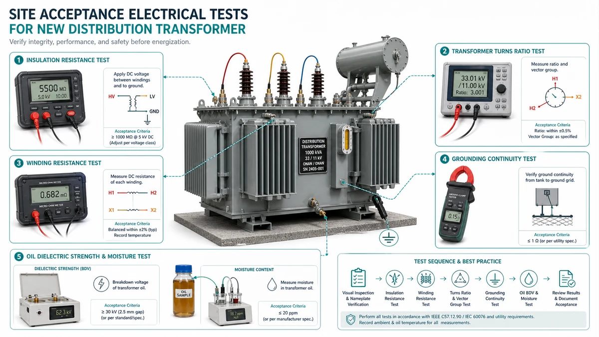
These three electrical tests establish the baseline condition of the unit as received. Running them before energization catches factory defects, shipping damage, and moisture ingress that visual inspection alone will miss.
Recommended test sequence:
1. Winding resistance first – generates no residual charge
| Test | Parameter | Minimum Akzeptabel | Warning Zone | Rejection Criterion | Abhilfemaßnahmen |
|---|---|---|---|---|---|
| IR | IR60 HV-to-ground (corrected to 20 deg C) | >=1,000 MOhm | 500-999 MOhm | <500 MOhm | Investigate moisture; oil sample; dry-out if confirmed |
| IR | IR60 LV-to-ground (corrected to 20 deg C) | >=100 MOhm | 50-99 MOhm | <50 MOhm | Check bushing surfaces; breather condition; oil level |
| PI | HV or LV winding | >=2.0 | 1.5-1.99 | <1.5 | Defer energization; oil dielectric and moisture-content test |
| IR | HV-to-LV inter-winding (corrected to 20 deg C) | >=1,000 MOhm | 500-999 MOhm | <500 MOhm | Inspect for oil contamination or winding displacement |
| TTR | Deviation from nameplate ratio | <=0.5% on principal tap | 0.5-1.0% | >1.0% on any tap | Verify tap position; return to manufacturer if confirmed |
| TTR | Phase-to-phase ratio balance (3-phase units) | <=0.5% spread | 0.5-0.8% | >0.8% spread | Suspect shorted turns; perform DGA on oil sample |
| Winding resistance | Phase balance, HV winding | <=1.0% deviation between phases | 1.0-2.0% | >2.0% | Check terminals; re-torque; inspect tap-changer contacts |
| Winding resistance | Phase balance, LV winding | <=1.0% deviation between phases | 1.0-2.0% | >2.0% | Inspect LV busbar connections; check for broken strands |
| Winding resistance | vs. factory test record (temp-corrected) | <=2.0% deviation | 2.0-5.0% | >5.0% | Investigate contact resistance or loose internal connection |
Before proceeding to the switching sequence, every protection relay, control circuit, and auxiliary system must be verified in isolation and then as an integrated loop. Skipping this phase is the most common cause of a missed trip or false trip during initial energization.
| Check Item | Verfahren | Akzeptanzkriterium |
|---|---|---|
| Relay CT polarity and ratio | Secondary or primary injection at rated tap | CT ratio within +-0.5%; polarity confirmed at relay terminal |
| Phase overcurrent pickup (51) | Secondary current injection | Operates at set pickup +-5% |
| Earth fault pickup (51N/50N) | Injection via neutral CT | Operates at set pickup; no operation below 0.9x pickup |
| Inrush restraint (2nd harmonic blocking) | Apply 2nd harmonic current >=15% of fundamental | Relay restrains; threshold matches setting sheet |
| Instantaneous element (50) | High-current injection at 1.05x and 0.95x set value | Operates above; restrains below |
| Trip output contact continuity | Multimeter across normally open contacts | <1 Ohm closed; open circuit when de-energized |
| Check Item | Verfahren | Akzeptanzkriterium |
|---|---|---|
| Slope characteristic | Dual-channel injection at operate and restraint coil | Boundary within +-5% of relay curve datasheet |
| Vector group compensation setting | Confirm relay software setting matches nameplate (Dyn11, Yyn0, etc.) | Setting matches; confirmed in relay file and stamped drawing |
| Zero-sequence blocking (HV side) | Inject zero-sequence on HV terminals | Relay does not operate |
| CT mismatch compensation | Calculate and enter tap correction factors | Differential spill current <5% of rated with balanced load injected |
| Through-fault stability | Inject rated through-fault current at slope-1 region | No trip; operate current below threshold |
| Check Item | Verfahren | Akzeptanzkriterium |
|---|---|---|
| WTI calibration | Inject current into thermal image heater at rated and 125% rated | Reading within +-3 deg C of calculated hot-spot |
| OTI calibration | Immerse bulb in controlled bath at 75 deg C and 100 deg C | Reading within +-2 deg C at each point |
| Buchholz alarm float | Introduce air into relay body via test valve | Alarm contact closes before trip float actuates |
| Buchholz trip float | Rapid oil surge via hand pump or tilt test | Trip contact closes; no mechanical binding |
| DC auxiliary supply | Voltmeter at relay terminals | Within -10% / +5% of rated auxiliary voltage |
| Trip coil continuity | Measure trip coil resistance vs. manufacturer data | Within +-15% of nameplate coil resistance |
| SCADA/RTU signal mapping | Verify each hardwired status and analog point against point list | All points match; no transposed or inverted signals |
Situation: During a distribution transformer SAT energization procedure at a 33/11 kV substation, secondary injection testing revealed that the inrush blocking threshold was set at 20% second harmonic. However, that firmware batch had a documented deviation: harmonic blocking engaged only above 22%, and the field team had used the previous firmware’s setting sheet.
Measured evidence: Injecting fundamental current with 18% second harmonic content-typical for energizing a lightly loaded distribution transformer-produced relay operation rather than restraint.
Once every SAT test result converts into a documented pass/fail decision, the team can advance to the switching sequence. A single unresolved item-winding resistance variance above tolerance, IR below minimum, or a failed turns-ratio reading-is sufficient cause to hold energization.
Physical and installation verification
– [ ] Transformer nameplate matches feeder design drawings (kVA, voltage, vector group, impedance)
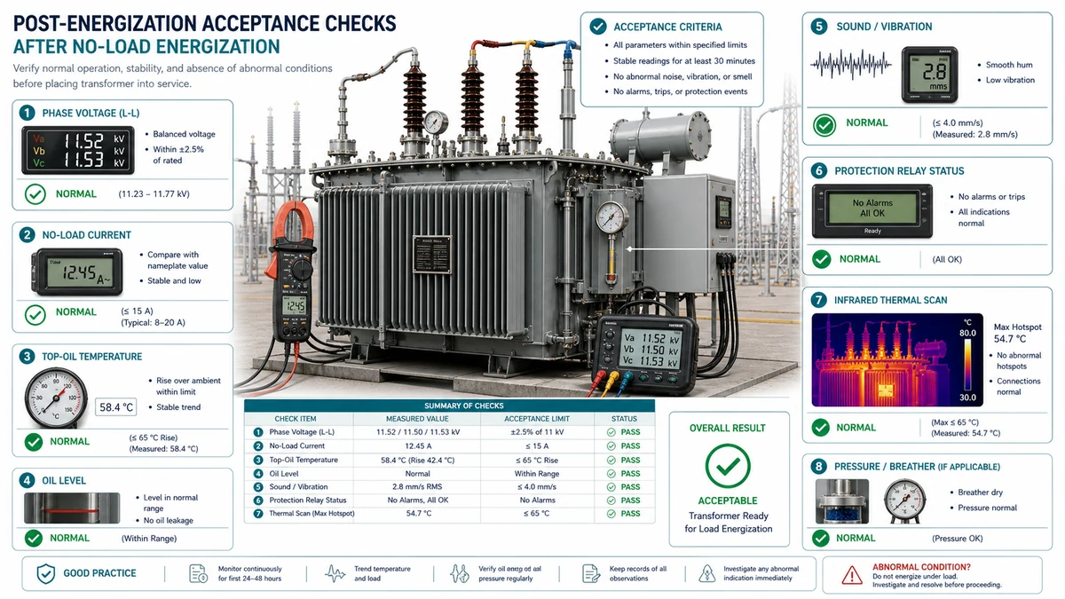
Once the transformer has held voltage without trip or alarm through the no-load observation period, the acceptance phase shifts to loaded performance confirmation.
| Parameter | Measurement Method | Pass Criterion | Investigate If |
|---|---|---|---|
| Output voltage (each phase) | True-RMS voltmeter at secondary terminals | Within +-2.5% of tap-adjusted nominal | Any phase deviates >2.5% |
| Voltage balance (three-phase) | % difference across phases | <=1.0% phase-to-phase | Imbalance >1.5% |
| Load current (each phase) | Clamp meter at secondary feeder | <=rated secondary current for applied load | Any phase >105% of expected draw |
| Current unbalance | Calculated from three-phase readings | <=10% per NEMA MG-1 guidance | Unbalance >10% |
| Neutral current (wye secondary) | Clamp meter on neutral conductor | <=10% of full-load rated current under balanced load | Neutral current >20% of FLA |
| Leistungsfaktor | Power analyzer at primary or secondary | Within 0.05 of design PF at test load | PF deviates >0.05 from baseline |
| THD (voltage) | Power quality meter | <=5% total harmonic distortion | THD >8% |
| Measurement Point | Werkzeug | Pass Criterion | Flag Condition |
|---|---|---|---|
| Temperatur des Oberöls | Dial thermometer or RTD | <=nameplate rated top-oil rise above ambient | >10 deg C above expected rise at test load |
| Tank surface | Wärmebildkamera | Uniform gradient from bottom to top | Any localized hotspot >15 deg C above adjacent tank surface |
| Primary termination lugs | Thermal camera | <=10 deg C above conductor temperature at same current | Any lug >20 deg C above conductor at same load |
| Secondary bushing connections | Thermal camera | <=10 deg C above conductor temperature | Any bushing >20 deg C above conductor |
| Cooling fins or radiators | Thermal camera | Uniform fin temperature within +-5 deg C row to row | Cold fins in a row (blocked or stuck cooling) |
| Intervall | Aktion | Zweck |
|---|---|---|
| 24 hours after energization | Log oil temperature, ambient, load current | Establish initial thermal baseline |
| 72 hours | Check all external connections for thermal discoloration; re-torque if flagged | Thermal cycling can loosen compression-type lugs |
| 7 Tage | Infrared scan at peak daily load | Captures thermal anomalies invisible at partial load during SAT |
| 30 Tage | Oil sampling for DGA on units >500 kVA | Detects early-stage internal faults developing under load |
| 30 Tage | Review protection relay event log | Confirms no unreported operation or near-operation events |
Procurement decisions made before a transformer ships directly determine how smoothly the field SAT will run. Waiting until equipment arrives on site to define test requirements, documentation expectations, or commissioning support responsibilities creates delays, cost disputes, and gaps in baseline data that can never be fully recovered.
The technical specification attached to the request for quotation is the only contractually enforceable place to define SAT scope. Minimum language should address:
| Zustand des Feldes | Specification Parameter to State | Impact on SAT Protocol |
|---|---|---|
| Altitude above 1,000 m | Site elevation in meters | Dielectric clearance and oil dielectric strength corrections required |
| Ambient temperature extremes | Min/max daily temperatures | Winding resistance baseline correction factors change |
| High humidity or coastal exposure | Relative humidity range; salt-fog classification | Tighter IR acceptance thresholds needed |
| Heavy industrial pollution | IEC pollution class or equivalent | Bushing leakage current tests become more critical |
| Frequent switching duty | Estimated daily switching cycles | Surge arrester coordination must be verified during SAT |
Verwenden Sie diese XBRELE-Referenzen, um die Feldentscheidung mit dem richtigen Produkt-, Test- und Beschaffungsablauf zu verbinden: XBRELE Produktseite, XBRELE Vakuum-Leistungsschalter-Programm, VCB-Rating-Leitfaden, VCB FAT/SAT Annahme-Checkliste, XBRELE Stromverteilertransformatorreihe.
Beispiel aus der Praxis: Bei einer Wartungsinspektion wurde bei einer Phase eine Abweichung von der Inbetriebnahme-Basislinie gemessen, während die beiden anderen Phasen stabil blieben. Das Team wiederholte die Messung mit verifizierten Leitungen, überprüfte das Timing und den Kontaktweg und nutzte die gemessene Abweichung, um ein Kontaktdruckproblem von einem allgemeinen Oberflächenreinigungsproblem zu unterscheiden.
The general industry threshold is >=1,000 MOhm for the HV winding to ground (corrected to 20 deg C) and >=100 MOhm for the LV winding to ground. However, the Polarization Index is often a more reliable condition indicator than the absolute IR value.
Inrush current typically peaks at 6-12x rated current and decays within 0.1-1.0 second for most distribution transformers. Inrush that does not decay within 2 seconds is abnormal and warrants de-energization, comparison of the excitation current measurement against the factory baseline, and DGA before a second energization attempt.
Technically yes, but doing so removes all baseline reference for the pre-energization electrical tests. Without the factory winding resistance and turns-ratio values, field deviations cannot be classified as pre-existing or installation-induced.
The most common causes are CT polarity reversal, incorrect vector-group compensation setting in the relay, inrush blocking threshold set too high relative to actual firmware behavior, or zero-sequence current not blocked on the HV delta winding. A secondary injection test performed before energization will catch all of these before the first switching event.
For units above 500 kVA or at voltage classes above 15 kV, a pre-energization DGA provides a baseline that enables detection of incipient faults developing under load. It is not universally mandated by standard, but without it a post-energization gas alarm cannot be interpreted reliably-there is no way to confirm whether gas was present before energization or generated by the energization event itself.