Need Full Specifications?
Download our 2025 Product Catalog for detailed drawings and technical parameters of all switchgear components.
Get CatalogDownload our 2025 Product Catalog for detailed drawings and technical parameters of all switchgear components.
Get CatalogDownload our 2025 Product Catalog for detailed drawings and technical parameters of all switchgear components.
Get Catalog
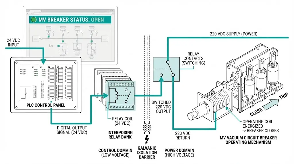
A PLC digital output module costs $300–500. The closing coil on a 12 kV vacuum circuit breaker draws 6 A steady-state at 220 VDC, with inrush peaks hitting 12–15 A during the first 20 milliseconds. Connect them directly, and you’ll replace that output module—once you understand why, you never make the mistake again.
Interposing relays form the essential bridge between programmable logic controllers and medium-voltage switchgear coils. They translate low-power digital signals into robust commands capable of actuating MV circuit breaker mechanisms while providing the galvanic isolation that protects sensitive automation electronics from the electromagnetic brutality of power apparatus switching.
The fundamental incompatibility between PLC outputs and MV operating coils creates three immediate failure paths when directly connected. Understanding this mismatch explains why interposing relays remain non-negotiable in every properly designed control system.
Standard PLC digital outputs deliver 24 VDC at 0.5–2 A maximum. MV circuit breaker coils demand something entirely different:
| Parameter | PLC Transistor Output | VCB Closing Coil | VCB Trip Coil |
|---|---|---|---|
| Operating voltage | 24 VDC | 110–220 VDC | 110–220 VDC |
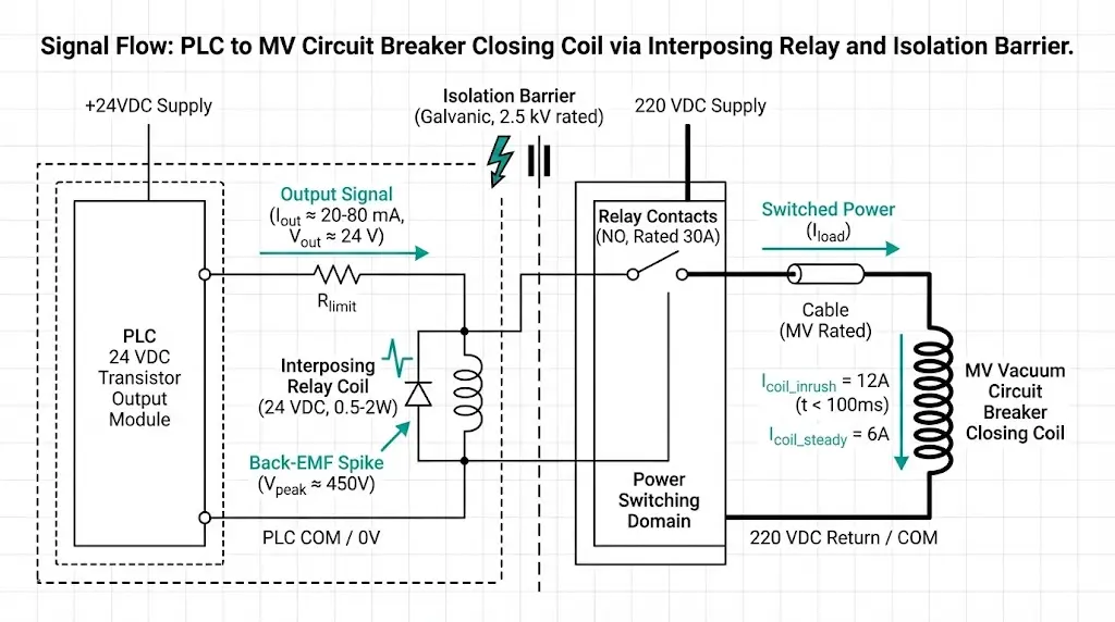
| Steady-state current | 0.5–2 A max | 3–8 A | 2–5 A |
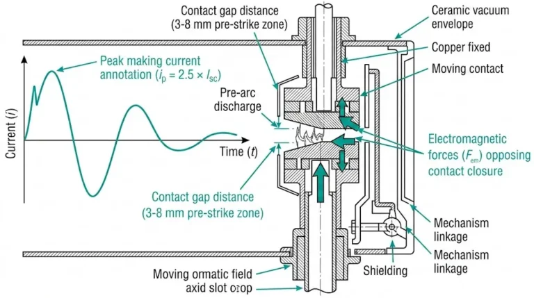
| Inrush current | Not applicable | 10–15 A (20 ms) | 8–12 A (10 ms) |
| Back-EMF on de-energization | Negligible | 400–600 V spike | 300–500 V spike |
The transistor output fails through overcurrent saturation during coil energization, voltage stress from back-EMF transients punching through the semiconductor’s rating, and conducted noise corrupting the PLC communication bus.
When current flows through an MV operating coil, energy stores in the magnetic field—typically 5–15 joules for a vacuum circuit breaker closing coil. The moment the control contact opens, this stored energy seeks release. A transistor rated for 30 VDC withstands perhaps 60 V absolute maximum. A 450 V transient destroys it in microseconds.
According to IEC 61131-2 (Programmable Controllers – Equipment Requirements), PLC digital outputs must maintain electrical isolation of ≥1500 Vrms between field circuits and internal logic. The interposing relay provides an additional isolation barrier, typically rated at 2500 Vrms per IEC 61810-1 (Electromechanical Elementary Relays), creating a combined isolation architecture that protects sensitive control electronics from transient voltages common in MV switching environments.
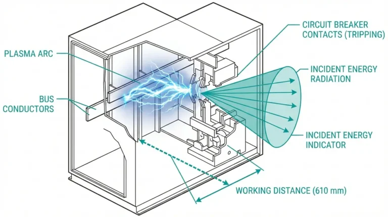
Substation environments compound these challenges. During bus faults, ground potential rise at the switchgear location can exceed 1 kV relative to the control room. Capacitive coupling from flashovers induces kilovolt-level transients on control wiring. Interposing relays provide 2–4 kV isolation between coil and contact circuits, physically separating the automation domain from the power apparatus domain.
Relay selection determines whether your control interface operates reliably for a decade or fails within two years. The specifications that matter most aren’t always the ones prominently displayed on data sheets.
Contact Rating and Material
The interposing relay must handle actual coil current, not catalog nominal values. For a closing coil drawing 6 A steady-state with 12 A inrush, calculate minimum contact rating at 150% of inrush—18 A in this case. Then apply a 40% derating factor for DC inductive loads. You need contacts rated for at least 30 A resistive equivalent.
Contact material selection directly impacts service life. Silver cadmium oxide (AgCdO) offers excellent arc resistance for DC coil switching. Silver tin oxide (AgSnO₂) provides a cadmium-free alternative with comparable performance. In mining applications with frequent switching cycles exceeding 20 operations daily, field testing demonstrated 40% longer contact life with tungsten-faced contacts versus silver alloy alternatives.
Coil Voltage Matching
Match the interposing relay coil to available PLC output capability:
| PLC Output Type | Relay Coil Voltage | Coil Power Range |
|---|---|---|
| Transistor (NPN/PNP) | 24 VDC | 0.5–1 W |
| Relay output | 24 VDC/VAC | 1–2 W |
| Triac output | 24–120 VAC | 0.5–1.5 W |
Low-power relay coils under 0.5 W suit direct transistor drive. Higher-power types may require an intermediate pre-interposing relay—creating a two-stage isolation chain for critical applications.
Response Time Budget
Every interposing relay adds delay. For protection applications, this delay must fit within coordination time margins:
Two-stage interposing configurations add 25–70 ms total delay. Compare this against protection coordination requirements before finalizing your design. In commissioning across petrochemical facilities, we’ve measured cumulative timing variations of ±5 ms that must be accommodated in coordination studies.
[Expert Insight: Relay Selection Field Experience]
- Undersized contacts fail within 18–24 months in heavy-duty applications; properly rated components achieve 10+ year service life
- Contact bounce must remain below 3 ms to prevent false retriggering of protection schemes
- Premium designs use bifurcated contacts with rhodium plating, achieving contact resistance below 50 mΩ
- Specify relays with at least one spare NO and one spare NC contact for future monitoring additions
Control logic architecture determines both reliability and diagnostic capability. Three patterns dominate MV switchgear applications, each addressing specific operational requirements.
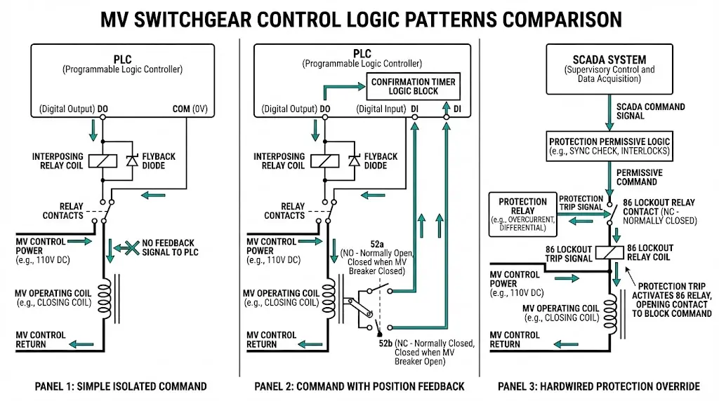
Pattern 1: Simple Isolated Command
The most basic configuration uses one interposing relay per control function. The PLC digital output energizes the relay coil; relay contacts switch the MV coil circuit. A flyback diode across the relay coil suppresses back-EMF.
This pattern suits non-critical auxiliary functions: heating control, indicator lamps, alarm circuits. Its limitation is obvious—no confirmation feedback. The PLC assumes command execution succeeded without verification.
Pattern 2: Command with Position Feedback
Production installations require closed-loop verification. The command signal passes through the interposing relay to the MV coil. Simultaneously, breaker auxiliary contacts (52a for closed position, 52b for open position) feed back to PLC digital inputs.
The logic implementation follows a clear sequence:
This pattern proves essential for vacuum contactors in capacitor switching applications where contact welding must be detected immediately. The feedback loop transforms blind command execution into verified operation.
Pattern 3: Hardwired Protection Override
SCADA-initiated control must never compromise protection system integrity. The standard approach interposes SCADA commands through hardwired protection logic—the protection relay’s output contact remains physically in series with the SCADA command path.
No software configuration can bypass a mechanically open contact. This principle protects against cyber compromise, programming errors, and communication failures. The lockout relay (86) reset verification, busbar protection zone interlocking, and synchronization check permissives all implement this pattern.
For safety-critical functions like earthing switch control where personnel safety depends on verified grounding, specify redundant interposing relays with series contacts.
When the interposing relay de-energizes an MV coil, stored magnetic energy must dissipate somewhere. Without proper suppression, that energy creates contact-destroying arcs.
Suppression Options Compared
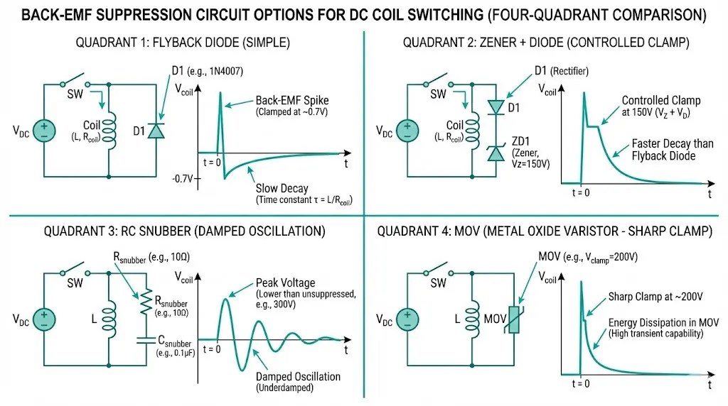
| Method | Advantages | Disadvantages | Best Application |
|---|---|---|---|
| Flyback diode | Simple, effective | Slows dropout 3–5× | Non-critical timing |
| Zener + diode | Controlled clamp voltage | Higher residual spike | Moderate timing requirements |
| RC snubber | AC/DC compatible | Component sizing critical | AC coil circuits |
| MOV | High energy absorption | Degrades over time | Surge-prone environments |
For trip coils where fast dropout matters, use Zener-diode suppression with breakdown voltage set at 0.7× coil voltage. A 220 VDC trip coil pairs with a 150 V Zener in series with a standard rectifier diode. This arrangement limits back-EMF while maintaining acceptable dropout speed.
Placement Matters More Than Selection
Mount suppression components at the coil terminals, not at the interposing relay contacts. Suppression devices installed at relay panels—meters away from the actual coil—provide marginal benefit due to wiring inductance between the snubber and the inductive load.
Coil-terminal mounting minimizes the suppressed loop inductance, protects all upstream switching devices in the circuit, and reduces conducted emissions on control wiring.
[Expert Insight: Suppression Circuit Field Observations]
- Missing suppression accelerates contact erosion dramatically—expect 60% reduction in contact life
- MOV suppressors require periodic replacement; degradation isn’t visible until failure occurs
- RC snubber sizing errors cause resonance; calculate values based on actual coil L and R measurements
- Document suppression component values during commissioning for maintenance reference
Modern SCADA protocols include mechanisms preventing spurious operations, but protocol-level security doesn’t eliminate the need for physical isolation.
Protocol Security Mechanisms
IEC 61850 GOOSE messaging incorporates priority tagging and state number sequencing to detect stale or replayed messages. DNP3 secure authentication prevents command injection; select-before-operate requires two-step confirmation before execution. Modbus TCP offers no native security—implement protection at the network layer or avoid it entirely for MV control applications.
Regardless of protocol sophistication, the interposing relay remains the final electromechanical gate. A compromised SCADA master can issue unlimited close commands; only the hardwired protection override (Pattern 3) prevents physical consequences.
Status Point Mapping for Diagnostics
Map interposing relay feedback contacts to SCADA status points for diagnostic visibility:
| Physical Point | SCADA Status | Alarm Condition |
|---|---|---|
| K1 auxiliary contact | CMD_ACTIVE | Energized > 2 s |
| 52a (breaker closed) | BKR_CLOSED | Disagrees with command |
| 52b (breaker open) | BKR_OPEN | Disagrees with 52a |
| Spring charged | READY | Not ready during close command |
This monitoring enables predictive maintenance. A relay showing increasing pickup time—measured as command-to-auxiliary-contact delay—indicates coil degradation before complete failure. Trending this data across quarterly intervals reveals developing problems months before they cause operational impact.
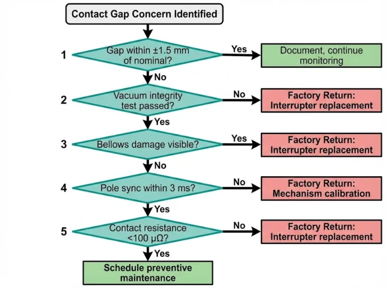
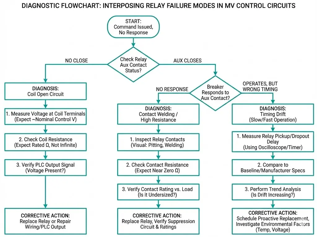
Three failure modes account for 85% of interposing relay problems in MV control circuits. Systematic diagnosis prevents unnecessary component replacement.
Relay Coil Open Circuit
Symptom: Command issued from PLC, no mechanical response, interposing relay auxiliary contact never closes.
Diagnostic sequence:
Root cause pattern: Coil insulation breakdown from capacitive coupling during bus faults. Long control cable runs to remote switchgear concentrate this risk. Install surge arresters on control cables exceeding 50 meters.
Contact Welding
Symptom: Breaker closes on command but will not open; interposing relay appears functional during coil energization test.
Investigation: Contacts may weld under high inrush current when rating is marginal, suppression is missing, or contact bounce allows multiple arc strikes during closure.
Prevention: Specify contact rating at minimum 150% of expected inrush. For safety-critical applications, use redundant interposing relays with series contacts—both must open to de-energize the load.
Timing Drift
Symptom: Protection coordination failures; breaker operates but not within expected time window.
Cause: Mechanical wear increases pickup time progressively. DC coil relays typically show 1–2 ms degradation per 100,000 operations.
Monitoring approach: Log timestamp difference between command output transition and breaker auxiliary contact response. Trend analysis reveals degradation trajectory before coordination margins are exceeded.
Physical installation quality determines long-term reliability more than component selection. Follow this checklist during commissioning:
Reliable control interfaces start with properly designed operating mechanisms. XBRELE manufactures vacuum circuit breakers and vacuum contactors with coil specifications optimized for PLC integration—including detailed inrush current data, recommended suppression circuits, and auxiliary contact configurations.
For engineers designing substation automation systems, our technical application support team provides guidance on control circuit integration, protection coordination, and SCADA interface requirements. We supply complete documentation packages covering electrical characteristics needed for interposing relay selection and control logic design.
Q: What minimum contact rating should I specify for an interposing relay controlling a VCB trip coil?
A: Calculate 150% of the coil inrush current, then apply a 40% derating for DC inductive loads—a 10 A inrush coil requires contacts rated for approximately 25 A resistive equivalent to prevent welding during repeated operations.
Q: How much delay does adding an interposing relay introduce to trip time?
A: Single-stage interposing typically adds 13–35 ms total latency (pickup plus dropout combined); two-stage configurations extend this to 25–70 ms, which must be verified against protection coordination study requirements.
Q: Where should back-EMF suppression components be physically installed?
A: Mount suppression devices directly at the MV coil terminals rather than at the relay panel—this placement minimizes loop inductance and protects all switching devices in the circuit path.
Q: Why can’t software interlocks replace hardwired protection overrides?
A: A mechanically open protection contact cannot be bypassed through software compromise, programming errors, or communication failures—the physical series connection guarantees the interlock regardless of digital system state.
Q: How can I detect interposing relay degradation before it causes a failure?
A: Monitor the time delay between command output transition and breaker auxiliary contact response, then trend this measurement quarterly—increasing delay indicates mechanical wear or coil degradation developing before complete failure.
Q: What contact material performs best for switching DC coils in frequent-operation applications?
A: Silver cadmium oxide (AgCdO) provides excellent arc resistance for DC switching duty; tungsten-faced contacts demonstrated 40% longer service life than silver alloys in applications exceeding 20 operations per day.
Q: Can standard Modbus TCP be used safely for MV breaker control?
A: Modbus TCP lacks native security features, making it unsuitable for direct MV control without additional network-layer protection—consider IEC 61850 or DNP3 with secure authentication for critical switching applications.