Need Full Specifications?
Download our 2025 Product Catalog for detailed drawings and technical parameters of all switchgear components.
Get CatalogDownload our 2025 Product Catalog for detailed drawings and technical parameters of all switchgear components.
Get CatalogDownload our 2025 Product Catalog for detailed drawings and technical parameters of all switchgear components.
Get Catalog

Vacuum circuit breaker lubrication failures split into two paths: under-lubrication increases friction at pivot points until the mechanism binds mid-stroke; over-lubrication causes grease migration onto insulating surfaces, creating tracking paths. Both paths end at the same destination — a breaker that fails during fault clearing.
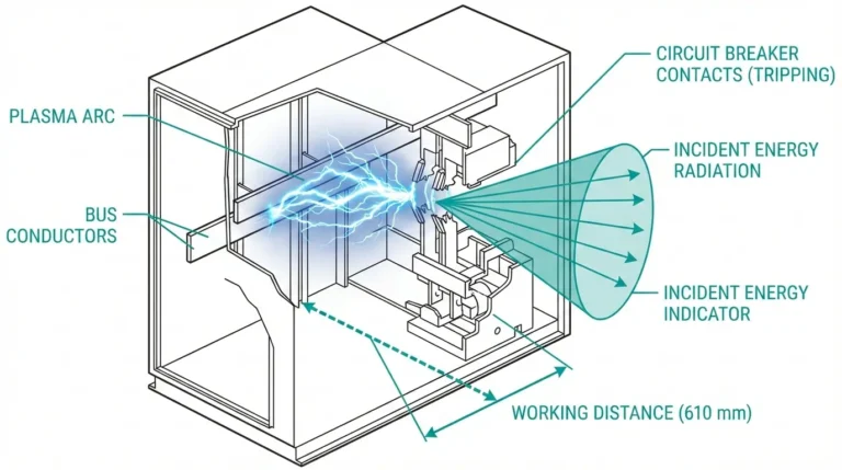
Field maintenance records across 50+ substation overhauls show approximately 40% of mechanism-related failures trace directly to lubrication problems — not worn contacts, not depleted vacuum. Lubrication. A spring-operated VCB can interrupt 31.5 kA fault current in under 60 milliseconds, but only if the operating mechanism actually moves.
This guide provides a precise lubrication map for spring-operated VCB mechanisms, identifies zones where lubricant must never touch, and delivers a diagnostic framework for sticky mechanism root causes.
Before opening a grease gun, understand what moves inside a vacuum circuit breaker operating mechanism. Spring-operated designs dominate 12–40.5 kV applications, and each contains several friction-critical assemblies.
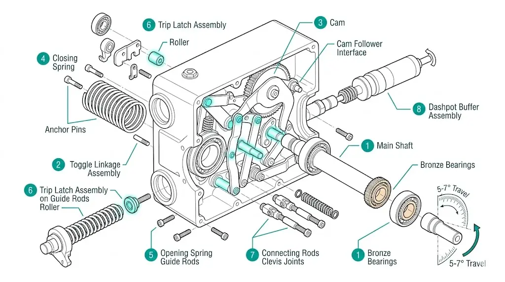
The charging motor drives a cam or gear train. Cam followers ride against hardened steel profiles under contact pressures reaching 15–25 MPa. Spring anchor pins transmit stored energy — typically 800–2,500 N during closing operations.
Pre-compressed springs mount on guide rods. The release latch engages with the trip shaft. A dashpot or buffer absorbs kinetic energy at stroke end.
The main shaft rotates approximately 5–7 degrees during each operation, with bearings experiencing rotational speeds of 50–100 rad/s during switching. Connecting rods transfer motion to each pole. Toggle links amplify force at the vacuum interrupter drive rod, with pivot points experiencing sliding friction under substantial load.
Roller latches hold the mechanism in closed position. The trip coil armature strikes the latch to initiate opening. Reset springs return latches to armed position.
Each joint, pivot, and sliding surface represents a potential friction point. However, not every friction point requires lubrication — and some must remain completely dry.
[Expert Insight: Friction Behavior in Operating Mechanisms]
- Properly lubricated steel-bronze bearing interfaces maintain friction coefficients below 0.15; contaminated surfaces can exceed 0.4
- Wear rates at mechanism pivot points typically range from 0.001–0.005 mm per 1,000 operations under proper lubrication
- When lubrication degrades, wear rates increase by 5–10×, accelerating mechanism failure
- Toggle linkage pins are particularly susceptible to fretting wear from small oscillatory movements during spring charging cycles
The following locations require periodic lubrication in most spring-operated VCB mechanisms. Always consult the specific manufacturer’s maintenance manual, as designs vary significantly between VS1, ZN85, and ZW32 series configurations.
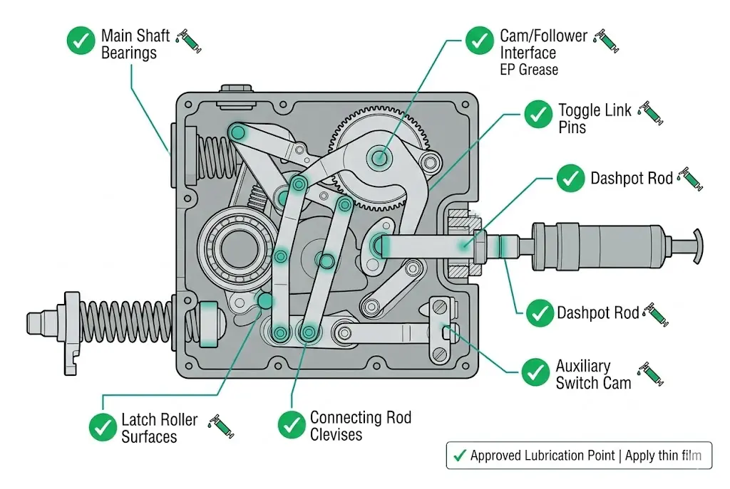
The main shaft assembly operates with bearing clearances of 0.02–0.05 mm. Apply a thin film — enough to coat the bearing surface, not fill the cavity. This prevents metal-to-metal contact while maintaining precise positioning critical to consistent contact travel.
The charging cam experiences high Hertzian contact stress. Use EP (extreme pressure) grease rated for steel-on-steel contact. The cam profile controls contact velocity during closing (0.8–1.2 m/s) and opening (1.5–2.5 m/s) sequences. Wipe old grease residue before applying fresh lubricant — layering new over degraded grease accelerates contamination.
Toggle joints multiply mechanical advantage but concentrate stress on pin surfaces. Without adequate lubrication, these pins develop galling and surface scoring that increases operating force by 15–25% within 2,000 operations. Apply grease through the fitting or disassemble and coat manually during overhaul.
Where connecting rods attach to the main shaft arm and pole unit drive rods, clevis pins pivot under load. Light grease prevents galling and ensures consistent operating speed across all three poles — pole-to-pole timing spread exceeding 3 ms typically traces back to differential clevis pin friction.
The roller latch holds significant spring force. A dry roller surface increases trip force requirements and causes inconsistent trip timing. Apply a small quantity of grease to the roller and its mating latch surface.
Hydraulic dashpots have separate oil fill requirements. Mechanical buffers with sliding rods need light lubrication to prevent scoring and maintain consistent energy absorption at stroke end.
The auxiliary switch assembly tracks mechanism position. Its cam surface should receive a thin grease film. In our field experience across multiple 12 kV switchgear installations, dried lubricant on auxiliary switch cams causes timing deviations of 5–15 ms — enough to affect protection relay coordination in differential protection schemes.
Field Note: A common mistake is applying grease only to visible external points while neglecting internal linkage pins. During overhaul, disassemble the linkage train and inspect each pin for wear scoring before re-lubricating.
Knowing where lubricant must never be applied is equally important. Grease in these locations causes insulation degradation, mechanism malfunction, or accelerated wear — and the damage is often not immediately visible.
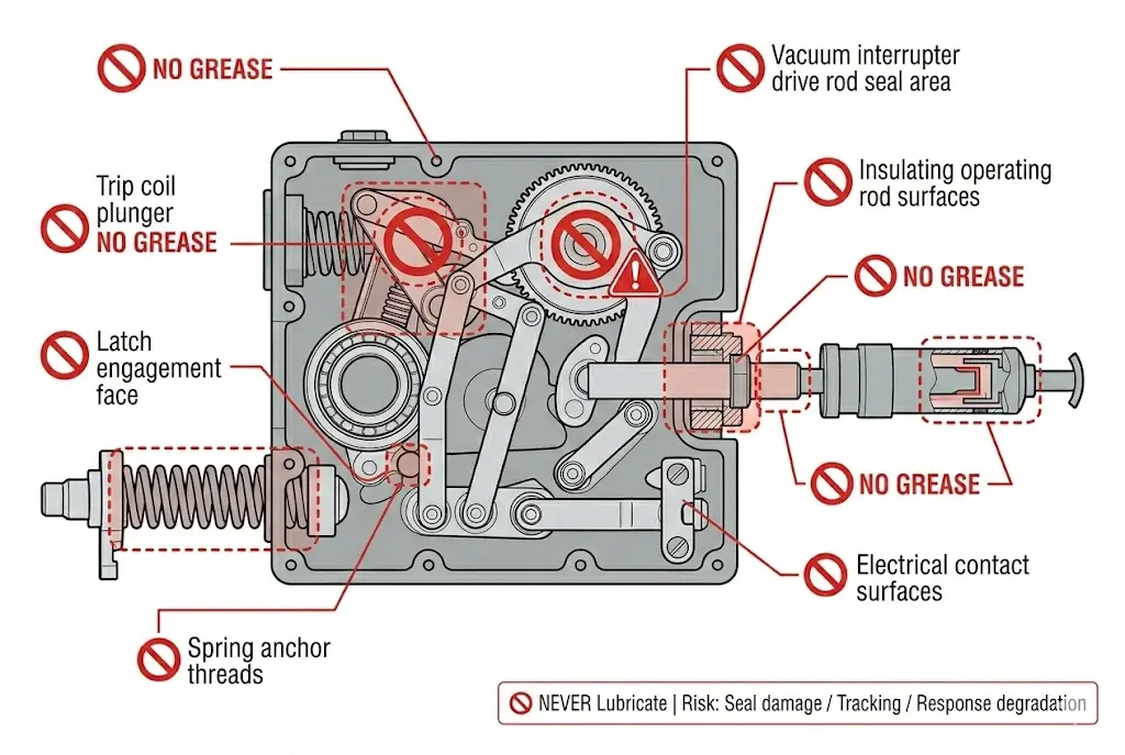
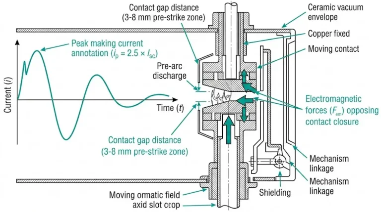
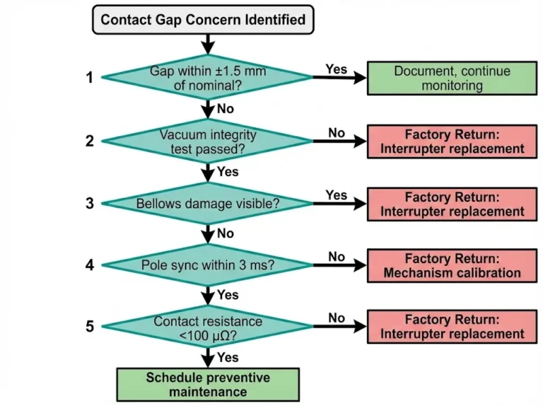
The bellows seal where the drive rod enters the vacuum interrupter envelope is engineered for dry operation. Grease contamination can attack the bellows material and compromise the hermetic seal. A breached bellows seal means loss of vacuum integrity — the interrupter must be replaced. Never allow lubricant near this zone.
Epoxy or fiberglass insulating rods connect the mechanism to pole units across the phase-to-ground insulation barrier. Grease attracts conductive dust, creates tracking paths, and degrades creepage distance below the required dielectric integrity per IEC 62271-1 clearance requirements. Clean these rods — do not lubricate them.
The trip coil armature must move freely within the coil bobbin. Grease increases viscous drag, slowing trip response. Worse, grease can migrate into the coil windings and cause thermal degradation. This surface should remain clean and dry.
Same principle as the trip coil. Electromagnetic actuators rely on minimal air gap and free armature movement. Contamination increases closing time and reduces available force, potentially causing a failed close under low control voltage conditions.
While latch rollers need lubrication, the latch face engagement surfaces present a different case. Lubricant on trip latch faces reduces holding force by 25–35%, potentially causing unintended releases under vibration or mechanical shock.
Threaded fasteners securing spring anchors should be torqued dry or with thread-locking compound per specification. Grease on threads reduces effective friction coefficient, potentially causing fastener loosening under cyclic loading.
Secondary circuit terminals, grounding contacts, and control wiring connections must remain grease-free. Oil or grease attracts conductive dust, creating tracking paths on auxiliary switch contacts and increasing contact resistance over time.
| Zone | Status | Reason |
|---|---|---|
| Main shaft bearings | ✅ Grease | Friction reduction |
| Cam/follower interface | ✅ EP grease | High contact stress |
| Toggle link pins | ✅ Grease | Prevent galling |
| Vacuum interrupter seal | ❌ Never | Bellows damage risk |
| Insulating rods | ❌ Never | Tracking path creation |
| Coil plungers | ❌ Never | Response time degradation |
| Latch face surfaces | ❌ Never | Reduced holding force |
[Expert Insight: Temperature Effects on Lubrication]
- In outdoor installations, mechanism temperatures range from −25°C to +55°C, causing lubricant viscosity changes of 100:1 or greater
- Mineral-based lubricants typically harden within 3–5 years in outdoor installations
- Synthetic alternatives maintain viscosity for 8–10 years under similar conditions
- Lubricant film thickness at bearing surfaces varies directly with viscosity — cold starts can allow metal-to-metal contact before the mechanism reaches operating temperature
When a VCB mechanism operates sluggishly, fails to latch, or requires excessive manual force, systematic diagnosis identifies the root cause faster than random disassembly. Work through symptoms in order before opening the mechanism.
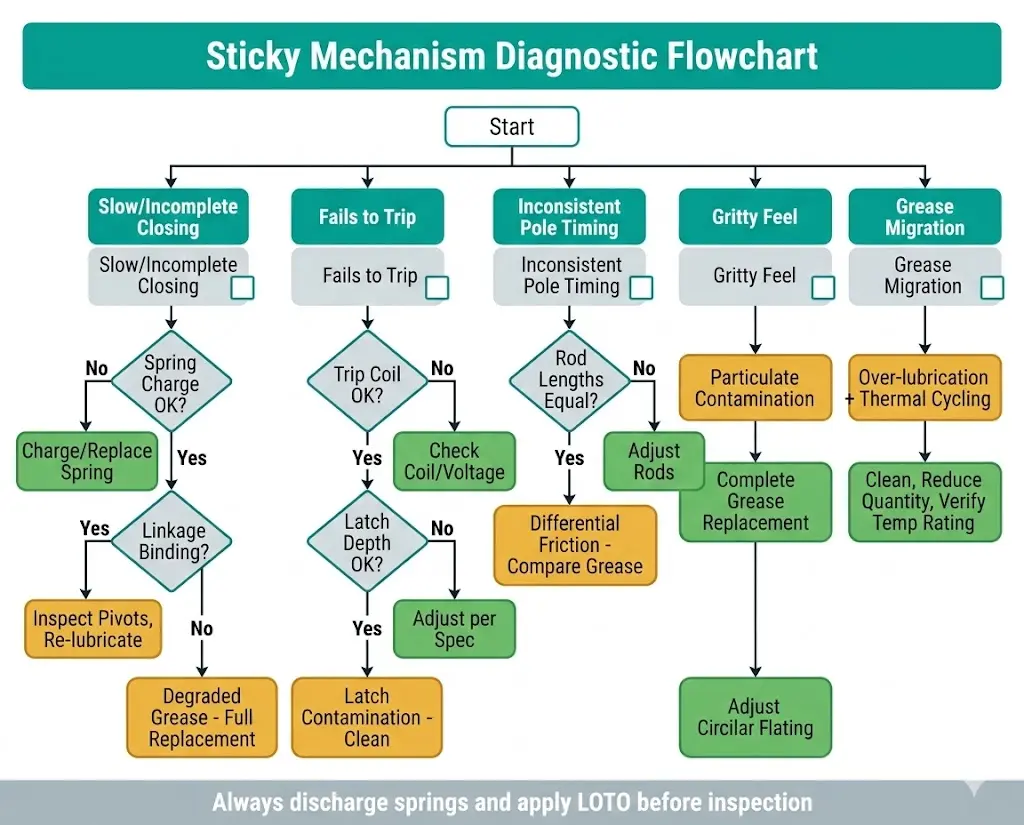
Check first: Closing spring charge status. A partially charged spring delivers insufficient energy for full contact travel.
Check second: Linkage binding. Manually rotate the main shaft (with springs discharged and safety locks engaged). Feel for rough spots through the travel range — binding at specific angles indicates a worn or contaminated pivot.
Check third: Old grease contamination. Degraded grease becomes paste-like or hardens, dramatically increasing friction. Look for amber or brown discoloration of originally light-colored grease.
Check first: Trip coil electrical function. Verify coil resistance (typically 50–200 Ω depending on rated voltage) and supply voltage at the coil terminals during a trip attempt.
Check second: Latch engagement depth. An over-engaged latch requires excessive trip force beyond the coil’s rated output.
Check third: Contamination on latch surfaces. Dust mixed with migrated lubricant creates a sticky film that increases release force beyond trip coil capability — a failure mode we’ve observed in coastal installations with high salt fog contamination.
Check first: Connecting rod length adjustment. Unequal rod lengths cause timing spread across phases.
Check second: Differential friction. One pole’s linkage may have more contamination or wear than others. Compare grease condition at each pole’s clevis pins.
Check third: Contact erosion variation. Unequal contact wear changes effective travel. Review vacuum circuit breaker ratings for contact wear assessment guidance.
Root cause: Contaminated grease with particulate ingress. Desert or high-dust environments accelerate this degradation. Complete grease removal and replacement required — do not simply add fresh grease over contaminated material. Adding clean grease over contaminated grease dilutes but does not eliminate the abrasive particles.
Root cause: Over-lubrication combined with thermal cycling. Excess grease liquefies slightly during temperature rise and migrates via capillary action. Remove migrated grease with appropriate solvent, reduce grease quantity at source, and verify grease temperature rating matches installation environment.
Not all greases perform equally in VCB mechanisms. Selection criteria span base oil chemistry, thickener type, and additive package — and the wrong choice can cause failures faster than no lubrication at all.
Mineral oil base suits moderate temperatures (−20°C to +80°C ambient) and offers economical pricing. Synthetic PAO base extends the operating range (−40°C to +120°C) with better oxidation resistance — the preferred choice for outdoor switchgear in extreme climates. Silicone base provides wide temperature tolerance but poor load capacity; avoid for high-stress cam surfaces.
Lithium complex serves as general purpose with good water resistance. Polyurea offers excellent high-temperature stability and long service life — commonly specified for sealed-for-life bearing applications. Calcium sulfonate provides superior corrosion protection for outdoor installations in marine or industrial environments.
EP (extreme pressure) additives are required for cam/follower and toggle pin applications. Avoid greases with graphite or MoS₂ fillers unless specifically called out in the manufacturer’s maintenance manual — these conductive particles create problems near insulating surfaces.
Never mix grease types without verifying compatibility. Lithium and polyurea greases are generally incompatible — mixing creates a soft, runny mixture that loses load-bearing capacity. When changing grease types during overhaul, completely remove all old grease before applying new. Field testing showed that mixing incompatible greases reduced operating mechanism reliability by approximately 40%.
| Parameter | Typical Specification |
|---|---|
| NLGI Grade | 2 (standard) or 1 (cold climate) |
| Temperature Range | −30°C to +130°C minimum |
| Four-ball weld load | >250 kg |
| Drop point | >180°C |
Maintenance intervals depend on operating frequency, environment, and criticality. According to IEC 62271-100, vacuum circuit breakers must maintain reliable operation for mechanical endurance ratings of 10,000 operations minimum (M1 class), with some designs rated for 30,000 operations (M2 class). Achieving this service life requires disciplined tribological management throughout the breaker’s operating history.
Interval Framework
| Service Level | Trigger | Scope |
|---|---|---|
| Routine Inspection | Annual or 1,000 operations | Visual check, timing verification, no disassembly |
| Intermediate Service | 3–5 years or 5,000 operations | Partial disassembly, re-grease critical points |
| Major Overhaul | 10–12 years or 10,000 operations | Full disassembly, 100% grease replacement |
Re-lubrication Procedure
When planning parts procurement for major overhauls, the VCB RFQ checklist provides a comprehensive specification framework covering mechanism components, contact assemblies, and auxiliary parts.
Maintaining vacuum circuit breaker mechanisms requires the right parts, correct lubricants, and access to engineering support when diagnostic questions arise. Sourcing from the original equipment manufacturer or a qualified supplier ensures dimensional compatibility and material specifications are met.
XBRELE supplies replacement mechanism components for VS1, ZN85, ZW32, and ZW20 series breakers:
Our technical team provides mechanism overhaul guidance, timing adjustment procedures, and grease compatibility recommendations specific to your installation conditions and operating environment.
Contact XBRELE for mechanism parts and overhaul support →
Q: How often should VCB mechanism grease be replaced?
A: For typical service conditions, perform intermediate re-greasing every 3–5 years or 5,000 operations; schedule a major overhaul with complete grease replacement at 10–12 years or 10,000 operations. Adjust intervals shorter for outdoor installations in high-humidity, salt fog, or high-dust environments.
Q: Can general-purpose automotive grease work on VCB mechanisms?
A: Automotive greases typically lack the EP additives and temperature stability required for mechanism cam surfaces and toggle pins. Use greases meeting the manufacturer’s specification for NLGI grade, temperature range, and four-ball weld load — substituting without verification risks accelerated wear within 1,000–2,000 operations.
Q: What causes grease to migrate onto insulating surfaces?
A: Over-application combined with thermal cycling liquefies excess grease, which then travels via capillary action to unintended areas. Applying specified quantities (2–3 grams per point) and using temperature-appropriate formulations significantly reduces migration risk.
Q: How can I tell if mechanism grease has degraded?
A: Degraded grease shows color change from original (typically white or light amber turning brown or black), consistency change from smooth to grainy or hardened, and may emit an acidic odor indicating oxidation. Any of these signs warrants immediate replacement rather than top-up.
Q: Why does my mechanism trip force increase over time?
A: Increasing trip force typically indicates lubricant degradation on latch roller surfaces, dust accumulation mixing with grease to form abrasive paste, or surface wear on latch engagement faces. Inspect and clean these areas during routine maintenance before the condition progresses to a trip failure.
Q: Is silicone grease acceptable for toggle link pins?
A: Silicone grease offers wide temperature tolerance but lacks the load-bearing capacity required for high-stress pivot points under 15–25 MPa contact pressure. EP-rated lithium complex or synthetic PAO greases provide better protection against galling at toggle joints.
Q: What happens if I mix different grease types during top-up?
A: Incompatible greases — such as lithium-based mixed with polyurea — can soften, separate, or lose load-bearing properties. Always verify compatibility using the manufacturer’s grease compatibility chart, or completely remove existing grease before switching formulations.