Benötigen Sie die vollständigen Spezifikationen?
Laden Sie unseren Produktkatalog 2025 herunter, um detaillierte Zeichnungen und technische Parameter aller Schaltanlagenkomponenten zu erhalten.
Katalog anfordernLaden Sie unseren Produktkatalog 2025 herunter, um detaillierte Zeichnungen und technische Parameter aller Schaltanlagenkomponenten zu erhalten.
Katalog anfordernLaden Sie unseren Produktkatalog 2025 herunter, um detaillierte Zeichnungen und technische Parameter aller Schaltanlagenkomponenten zu erhalten.
Katalog anfordern
Coil burnout in vacuum contactors follows a predictable failure path: heat accumulates in the winding until insulation breaks down, inter-turn shorts develop, and the coil fails. The trigger is almost always traceable to an electrical or mechanical condition that was not measured, not anticipated during design, or not corrected during commissioning. This guide covers root cause identification, control circuit design review, thermal environment assessment, hold-current architecture selection, protective relay integration, and procurement verification.
Use this table as a first-pass triage tool. A symptom matching more than one row requires addressing all matching conditions simultaneously.
| Symptom | Erster Test | Wahrscheinliche Grundursache | Nächste Aktion |
|---|---|---|---|
| Coil burns out within days of installation | Measure control voltage at coil terminals during energization | Voltage sag at pull-in below 85% rated | Upsize control transformer or reduce burden on control circuit |
| Coil burns out after months of normal service | Log control voltage over 24 h | Sustained overvoltage above 110% rated | Add voltage-regulating transformer or adjust tap setting |
| Coil hot but contactor closes normally | Count operations per hour against manufacturer’s rated duty | Hohe Schaltfrequenz | Reduce cycle rate or specify a higher-duty coil |
| Coil burns out with visible pole-face debris | Inspect pole faces and guide pins | Armature blocked open | Clean pole faces, replace worn guides, add enclosure sealing |
| Intermittent burnout with no clear pattern | Measure voltage drop across each control circuit segment under load | Loose control wiring causing voltage drop | Re-torque terminals, replace undersized control conductors |
| Coil resistance reads low before full burnout | Measure coil resistance and insulation resistance to ground | Thermal cycling insulation degradation | Replace coil; investigate root thermal cause before re-energizing |
| Instrument or Reference | Purpose in Coil Burnout Diagnosis |
|---|---|
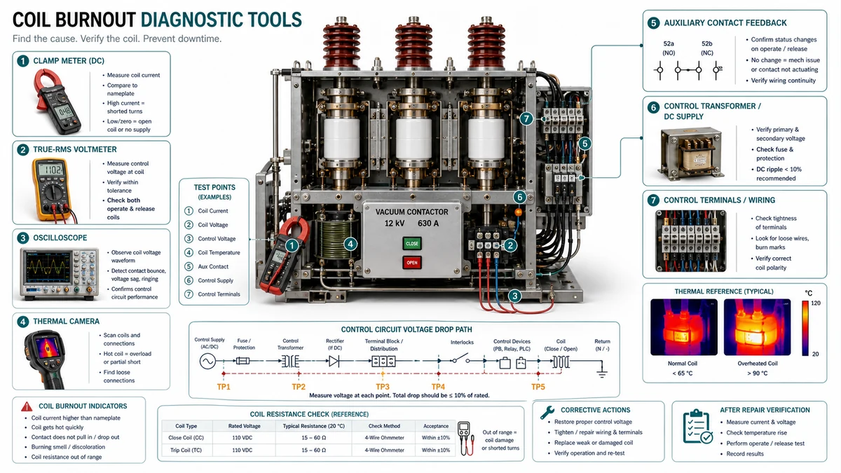
| Clamp-type current meter | Measure pull-in and hold-in coil current; verify economy circuit transition |
| True-RMS-Multimeter | Measure coil terminal voltage under load; check voltage drop across connections |
| Power quality analyzer or data logger | Capture voltage sag during inrush; log 24 h supply quality |
| Insulation resistance tester (500 V or 1000 V DC) | Measure coil winding insulation resistance to ground before and after suspected thermal event |
| Durchgangswiderstandsprüfer (Mikro-Ohm-Bereich) | Verify auxiliary contact resistance; flag elevated resistance in control circuit path |
| Calibrated thermocouple or thermal data logger | Measure enclosure ambient temperature at coil level during peak load |
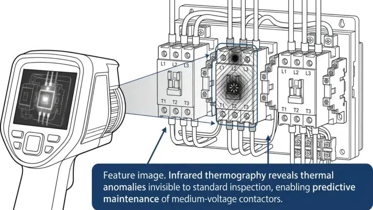
| Infrared thermography camera | Identify hot spots on adjacent heat sources; not a substitute for direct air temperature measurement |
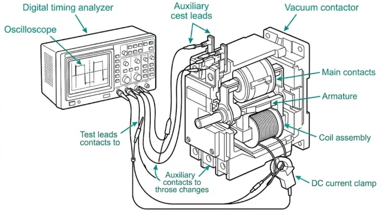
| Timing analyzer or oscilloscope | Capture armature closure time; detect contact bounce causing repeated inrush events |
| OEM contactor datasheet and instruction manual | Confirm coil voltage tolerance, thermal class, duty rating, and economy circuit specifications |
| Project specification and single-line drawings | Verify design intent versus as-built control circuit conditions |
The four root causes account for the majority of field failures.
Sustained overvoltage. A coil rated 120 V AC running at 115% of rated voltage carries approximately 32% more thermal load than at rated conditions, steadily eroding insulation life over months of continuous operation.
Voltage sag during pull-in. If supply voltage sags below roughly 85% of rated during inrush, the armature may not fully seat. A partially seated armature keeps the air gap open, holds impedance low, and allows inrush-level current to persist indefinitely — the single most common burnout mechanism in medium-voltage switchgear applications.
| Zustand des Feldes | Mechanismus | Coil Failure Mode |
|---|---|---|
| Long cable runs to control panel | Resistive voltage drop under load | Chronic undervoltage at coil terminals |
| Shared control transformer with high-inrush loads | Voltage sag during motor starts | Intermittent pull-in failure, extended inrush |
| Undersized control transformer | Poor regulation under load | Sag at full load, swell at light load |
| Loose terminal connections | Intermittent resistance increase | Voltage drop plus arcing at connection point |
| Aging transformer with degraded regulation | Wide output swing | Overvoltage at light load, undervoltage at full load |
| Unfiltered rectified DC supply | High ripple content | Elevated RMS current, increased heating |
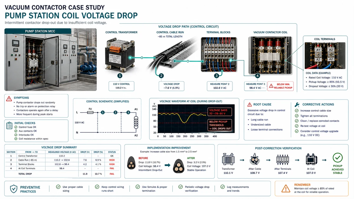
A water treatment facility reported three coil failures on the same vacuum contactor position over 18 months. Each failed coil showed discoloration consistent with thermal overload.
Ermittlungen: The control transformer also supplied the station’s PLC, HMI, and several auxiliary relays. Under full station load, transformer secondary voltage dropped to 101 V — within tolerance. However, measuring directly at the coil terminals revealed a corroded terminal block adding approximately 4-6 ohm of intermittent resistance, dropping coil terminal voltage to 94-98 V under normal conditions. During summer months, when enclosure ambient reached 45 deg C, connection resistance increased further, dropping coil terminal voltage to 81-84 V — well below the 85% minimum. The contactor was pulling in but not fully seating the armature on every cycle, extending inrush duration and overheating the coil.
Corrective action: Terminal block replacement; addition of a DIN-rail voltage monitoring relay set to lock out the control circuit below 88% and above 112% of rated voltage; quarterly connection resistance check added to the maintenance schedule. No further coil failures were reported over the following 24 months.
A control circuit review for coil burnout prevention follows a defined sequence. Each step produces a pass, flag, or fail decision.
| Zustand | Acceptable Range | Action if Outside Range |
|---|---|---|
| AC coil, nominal 120 V | 108-132 V (+/- 10%) | Investigate supply regulation or transformer tap |
| DC coil, nominal 24 V | 21.6-26.4 V (+/- 10%) | Check rectifier output and cable voltage drop |
| Voltage during inrush | Must not collapse below 85% of rated | Add hold-in relay or boost circuit |
| Coil terminal voltage vs. panel bus | Within rated band | Recalculate wire gauge if drop exceeds 5% |
Pass criterion: The coil can de-energize through at least one independent path under any single-fault condition.
| Suppression Type | Wo es punktet | Wo es riskant wird |
|---|---|---|
| RC snubber (AC coils) | Low cost, effective across wide frequency range | Incorrect RC values can cause re-strike or delayed dropout |
| Freewheeling diode (DC coils) | Eliminates spike cleanly | Extends dropout time; unacceptable in safety-critical de-energization |
| Transient voltage suppressor (TVS) | Fast clamping, defined clamp voltage | Must be sized for repetitive energy; undersized TVS degrades over time |
| Metal oxide varistor (MOV) | Handles high-energy transients | Degrades with each event; no visible failure indicator |
| Zener + diode combination (DC) | Faster dropout than freewheeling diode alone | Higher cost; polarity-sensitive installation |
Flag: No suppression present on a DC coil circuit.
| Protection Device | Funktion | Design Check |
|---|---|---|
| Control fuse | Protects wiring, not the coil | Confirm fuse rating does not exceed wire ampacity |
| Thermal overload on coil circuit | Detects sustained overcurrent | Verify trip class matches coil thermal time constant |
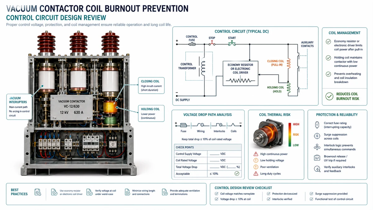
| Electronic coil driver with current limiting | Reduces inrush, holds at sealed current | Confirm driver output voltage and temperature rating |
| PTC thermistor in series with coil | Limits current on overtemperature | Verify reset behavior — some PTCs require manual reset |
| Finding | Schweregrad | Erforderliche Maßnahmen |
|---|---|---|
| Coil voltage outside +/- 10% at terminals | Hoch | Correct before energizing |
| No suppression on DC coil | Hoch | Install before energizing |
| Switching device undersized for inrush | Hoch | Replace before energizing |
| Continuous-duty application with intermittent-rated coil | Hoch | Replace coil or contactor |
| Suppression present but at wrong location | Mittel | Relocate to coil terminals |
| Fuse oversized relative to wire ampacity | Mittel | Replace fuse |
| Auxiliary contact resistance elevated | Mittel | Clean or replace contact block |
| No documentation of last coil replacement date | Niedrig | Record and establish inspection interval |
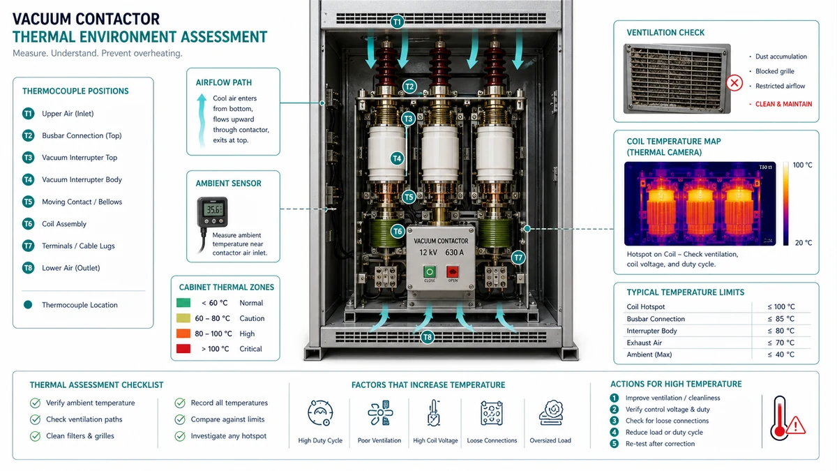
The Arrhenius rule of thumb for insulation aging states that every 10 deg C rise above the rated temperature halves insulation life. For a Class B insulation system (130 deg C limit), a coil running at 140 deg C has roughly half the expected service life.
| Thermal Condition | Measurable Indicator | Risikostufe | Abhilfemaßnahmen |
|---|---|---|---|
| Enclosure ambient <= 40 deg C, adequate ventilation | Thermocouple at coil level | Niedrig | Document baseline; no action required |
| Enclosure ambient 41-55 deg C, natural convection only | Internal air temp during peak load | Mäßig | Add forced ventilation or derate duty cycle |
| Enclosure ambient > 55 deg C | Measured internal air temp | Hoch | Relocate contactor, add heat exchanger, or use high-temperature coil variant |
| Adjacent heat sources within 150 mm | Infrared scan or thermocouple on enclosure wall | Moderate to High | Increase separation, add thermal barriers |
| Coil energized continuously in sealed enclosure | Duty cycle log plus enclosure temp rise | Hoch | Switch to DC coil with economy resistor or add forced cooling |
| Altitude > 2000 m above sea level | Installation altitude record | Mäßig | Derate per manufacturer altitude correction factor |
| Cyclic loading > 30 operations/hour | Operations counter plus thermal imaging | Mäßig | Verify coil duty rating; check for hot spots at coil terminals |
| Coil insulation class mismatched to environment | Nameplate class vs. measured ambient | Hoch | Replace with correct insulation class variant before energizing |
Pass: Measured enclosure ambient at coil level is <= 40 deg C under worst-case operating conditions; no unshielded heat-generating equipment within 150 mm; coil insulation class rating exceeds ambient plus expected self-heating; altitude correction applied above 2000 m; duty cycle within rated classification.
Marginal — Conditional Acceptance: Enclosure ambient is 41-55 deg C but forced ventilation verified to reduce internal temperature to <= 40 deg C; adjacent heat sources present but shielding confirmed. Marginal installations require follow-up thermal inspection within 90 days of commissioning.
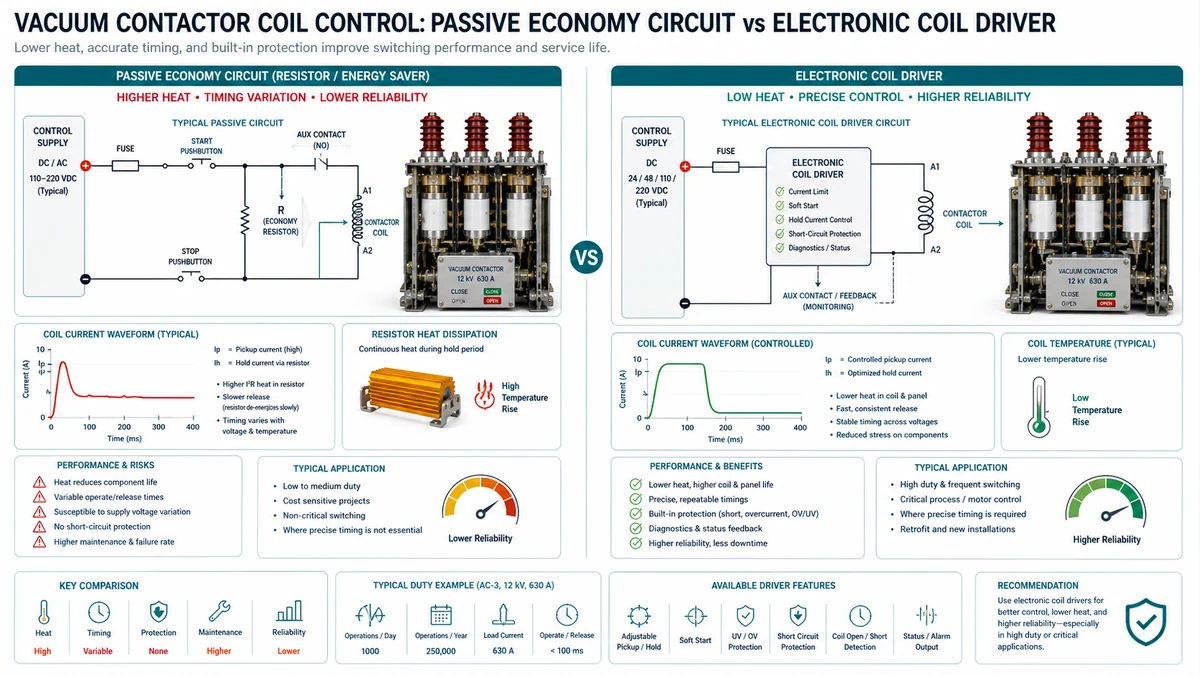
Reducing hold current after initial pull-in is one of the most direct interventions for coil burnout prevention. The decision is not whether to use a hold-current architecture, but which type survives the specific field environment long enough to justify its cost and complexity.
| Kriterium | Passive Economy Circuit | Electronic Coil Driver |
|---|---|---|
| Switching duty < 10 cycles/hr | Annehmbar | Preferred but not required |
| Switching duty > 30 cycles/hr | High risk (contact wear) | Bevorzugt |
| Supply voltage variation +/- 15% | Risk of under-hold at low end | Regulated output manages range |
| Ambient temperature > 50 deg C | Resistor derating required | Driver thermal derating required |
| Altitude > 2000 m | Resistor derating required | Check capacitor ratings |
| High vibration | Low risk (few components) | Requires conformal coat and vibration spec |
| Dusty or contaminated environment | Timing relay contacts at risk | Sealed module preferred |
| Power quality transients | Generally tolerant | Verify surge immunity rating |
| Maintenance skill level | Basic | Requires correct OEM replacement |
| Anfängliche Kosten | Unterer | Höher |
Passive economy circuits win in low-cycling, clean environments where maintenance resources are limited — a well-derated passive circuit with a sealed timing relay may carry lower long-term risk than a driver replaced with a non-OEM substitute during the first emergency.
Electronic coil drivers win in high-cycling, variable-voltage, or high-humidity applications. Specify drivers with armature-confirmation sensing to prevent reducing current before the armature has fully seated. For in-depth selection guidance for motor starting applications, refer to the vacuum contactor selection for motor starting applications post at XBRELE.
Protective relay integration represents the primary active defense layer. The architecture must interrupt damaging conditions before thermal limits are exceeded without introducing nuisance trips that mask legitimate fault conditions.
| Funktion | Primary Protection Offered | Wo es punktet | Wo es riskant wird |
|---|---|---|---|
| Coil current monitoring relay | Direct detection of overcurrent through winding | High-cycling duty, failed economy resistor | Calibration drift in high-vibration environments |
| Thermal overload relay on control circuit | Cumulative heat buildup detection | Frequent jogging or inching duty | Slow response to single catastrophic overcurrent event |
| Undervoltage relay (27) | Prevents coil from holding in during voltage depression | Sites with known sag conditions | Does not protect against overvoltage damage |
| Overvoltage relay (59) | Detects supply above coil rated maximum | Unregulated or generator-fed systems | May operate spuriously during capacitor bank energization |
| Auxiliary contact feedback logic | Verifies mechanical position matches commanded state | Detecting stalled armature or welded contacts | Requires reliable auxiliary contact; worn contacts give false signals |
| Anti-repeat timer | Limits close operations within a defined time window | Motor starter applications with high restart demand | Overly conservative settings delay legitimate restart |
| Economy circuit supervisory relay | Monitors transition to reduced hold current | All two-stage coil drive installations | Dependent on economy circuit component condition |
Stage 1 — Close Command Qualification: Three conditions in series must be satisfied before the coil energization path completes: control supply voltage within band (Relay 27 AND Relay 59 contacts closed); anti-repeat timer contact closed; auxiliary contact confirms open position.
Stage 2 — Inrush Period: Full coil voltage applied; timing relay begins counting maximum allowable pull-in period (typically 50-200 ms). If the auxiliary contact does not transition within this window, the coil path is interrupted and a “failed to close” alarm is asserted — directly addressing the stalled armature condition.
| Parameter | Acceptable Range | Basis |
|---|---|---|
| Undervoltage (27) pickup threshold | 85-90% of rated coil voltage | Below 85%, coil holds in unreliably; above 90%, nuisance trips on normal variation |
| Undervoltage (27) time delay | 1.0-3.0 s minimum | Prevents trip on transient sags during motor starting on same bus |
| Overvoltage (59) pickup threshold | 110-115% of rated coil voltage | Insulation ratings typically tested to 110%; 115% provides margin |
| Overvoltage (59) time delay | 0.5-1.0 s | Capacitor bank transient recovery voltages typically decay within 200 ms |
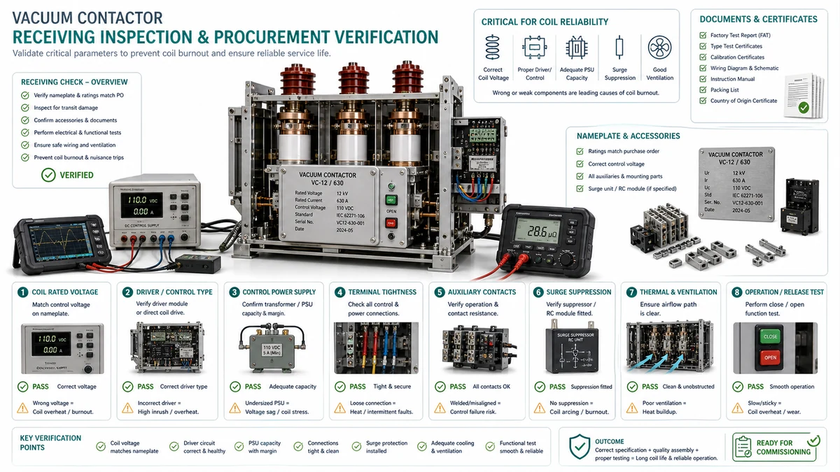
Purchasing a vacuum contactor without verifying its coil protection architecture is one of the most common sources of premature coil failure. The following confirmations reduce the probability of receiving a unit that depends entirely on the installation team to add protection that should have been engineered in from the start.
| Zustand des Feldes | What to Confirm With Manufacturer |
|---|---|
| Altitude above 1000 m | Derating factor for coil cooling and dielectric performance |
| Ambient temperature above 40 deg C | Coil thermal class (Class F or H minimum for hot environments) |
| High switching frequency (> 30 operations/hour) | Thermal duty cycle validation at actual switching rate |
| Corrosive or high-humidity enclosure | Coil moisture protection rating and conformal coating availability |
| DC control voltage from battery-backed UPS | Coil compatibility with DC source, ripple tolerance, polarity sensitivity |
| Vibration or shock (pumping, compressors) | Mechanical retention of coil connections and anti-vibration mounting |
Catalog-level confirmations:
– [ ] Economizer or two-stage coil drive confirmed as standard on supplied units
Verwenden Sie diese XBRELE-Referenzen, um die Feldentscheidung mit dem richtigen Produkt-, Test- und Beschaffungsablauf zu verbinden: XBRELE Produktseite, XBRELE Vakuum-Leistungsschalter-Programm, VCB-Rating-Leitfaden, XBRELE vacuum contactor range.
Für externen Methodenkontext vergleichen Sie die Site-Prozedur mit der öffentlichen IEEE C37.09 Normen Seite und wenden Sie dann das genaue OEM-Handbuch und die Projektspezifikation für die gelieferte Ausrüstung an.
Beispiel aus der Praxis: Bei einer Wartungsinspektion wurde bei einer Phase eine Abweichung von der Inbetriebnahme-Basislinie gemessen, während die beiden anderen Phasen stabil blieben. Das Team wiederholte die Messung mit verifizierten Leitungen, überprüfte das Timing und den Kontaktweg und nutzte die gemessene Abweichung, um ein Kontaktdruckproblem von einem allgemeinen Oberflächenreinigungsproblem zu unterscheiden.
The most common cause is a partially seated armature caused by voltage sag during pull-in. When control voltage drops below approximately 85% of rated during the inrush period, the armature may not fully close.
Check the manufacturer datasheet for two separate current or voltage ratings: a pick-up (pull-in) value and a hold (sealed) value. If only a single coil rating is listed, the unit likely lacks an economy function.
Take measurements in this sequence: (1) Coil terminal voltage under load during pull-in, captured over a 200 ms window to detect sag. (2) Coil resistance compared to nameplate to identify inter-turn shorts.