Need Full Specifications?
Download our 2025 Product Catalog for detailed drawings and technical parameters of all switchgear components.
Get Catalog
Download our 2025 Product Catalog for detailed drawings and technical parameters of all switchgear components.
Get Catalog Download our 2025 Product Catalog for detailed drawings and technical parameters of all switchgear components.
Get Catalog
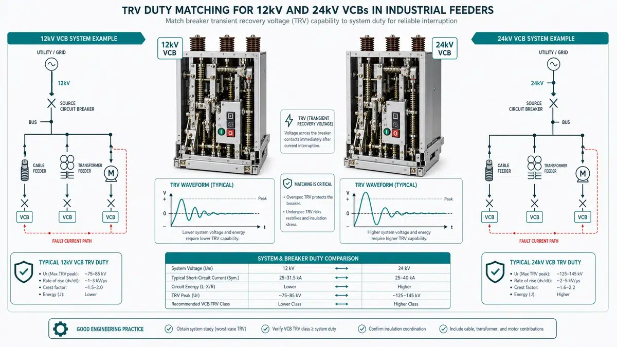
TRV duty matching for 12kV and 24kV VCBs is the process of verifying that a vacuum circuit breaker’s rated transient recovery voltage capability – defined by its peak voltage (Uc), rate of rise (RRRV), and time-to-peak (t3) – equals or exceeds the actual TRV envelope that the feeder circuit will impose during fault interruption. When that match fails, the breaker re-strikes across the still-hot vacuum gap, converting a cleared fault into a sustained or escalated fault event. This guide covers the calculation workflow, feeder topology comparison, mitigation options, and procurement checklist needed to resolve that problem in 12kV and 24kV industrial applications.
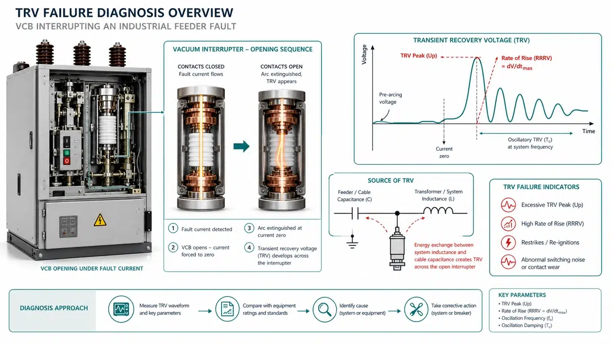
Before proceeding to calculations or fieldwork, use this table to triage symptoms against likely root causes.
| Symptom | First Test | Likely Root Cause | Next Action |
|---|---|---|---|
| Restrike during fault interruption | Pull relay event record; check for dV/dt spike 2-4 ms post-extinction | TRV peak or RRRV exceeds breaker rated envelope | Measure TRV with transient recorder; compare to IEC 62271-100 T100s envelope |
| Premature contact erosion (>50% depth before scheduled interval) | Count operations; inspect contact travel indicator | Repeated high-energy arcing from TRV mismatch or elevated RRRV | Perform TRV duty calculation; check first-pole-to-clear factor |
| Post-trip overvoltage alarms at motor terminals | Inspect surge arrester for signs of recent conduction | Motor contribution elevating TRV amplitude factor | Review earthing classification; check kaf against rated value |
| Oscillatory voltage transient on switching | Capture waveform at >= 1 MHz sample rate | Cable-OHL junction reflection creating double-peaked TRV | Simulate with EMTP; evaluate RC snubber at junction |
| Multiple re-ignitions on capacitor bank feeder | Measure capacitive current magnitude | Capacitive switching class mismatch (C1 applied where C2 required) | Verify breaker switching class; add pre-insertion resistor if needed |
| Instrument / Source | Application in TRV Duty Matching |
|---|---|
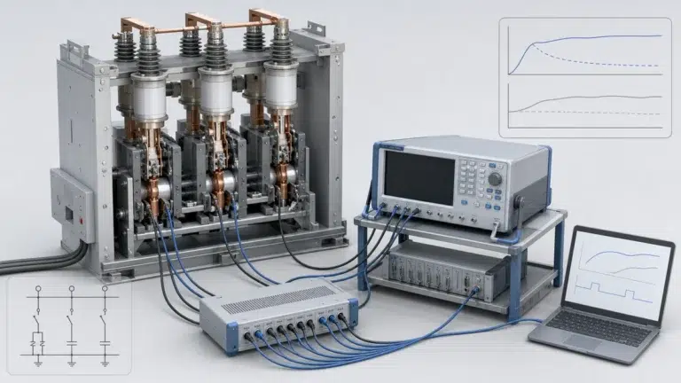
| Transient recorder (>= 1 MHz sample rate) | Measure RRRV and peak TRV at breaker terminals |
| High-bandwidth Rogowski coil (>= 5 MHz) | Detect chopping current in motor feeder applications |
| Contact resistance tester (micro-ohm range) | Track contact erosion trend between inspections |
| Insulation tester (polarization index capable) | Assess bushing and cable insulation degradation |
| EMTP-RV, ATP-EMTPE, or DIgSILENT PowerFactory | Simulate full TRV waveform for network-specific duty matching |
| IEC 62271-100 (current edition) | Authoritative test duty envelopes, four-parameter method, TRV worksheets |
| OEM breaker type-test certificate | Verified RRRV and Uc at each test duty (T10, T30, T60, T100) |
| Project specification / protection coordination study | Confirmed system earthing class, fault level, and cable data |
Standard TRV type tests in IEC 62271-100 and IEEE C37.09 assume a balanced three-phase short circuit at rated fault level through a defined source impedance. Industrial feeders deviate from this in several ways that directly affect TRV duty matching.
Short-line fault (SLF) and terminal fault asymmetry. Even 50-100 m of XLPE cable can raise the RRRV to values that challenge standard T10 duty ratings, because the cable acts as a transmission line with surge impedance of 30-50 ohm; travelling wave reflections produce RRRV values of 5-15 kV/micro-s on 12kV feeders.
Transformer-limited faults (TLF). When a VCB interrupts a fault near a step-down transformer secondary, leakage inductance reduces fault current while increasing oscillation frequency and peak TRV. RRRV can exceed 20 kV/micro-s and peak TRV may reach 2.0-2.5 pu on a 24kV system – making a fault that appears benign in relay terms dielectrically severe for the vacuum interrupter.
| Parameter | IEC 62271-100 T100s Reference | Typical 12kV Cable Feeder | Typical 24kV Motor-Transformer Feeder |
|---|---|---|---|
| First-pole-to-clear factor (kpp) | 1.3 pu | 1.3-1.5 pu | 1.3-1.5 pu |
| Amplitude factor (kaf) | 1.54 pu | 1.4-1.6 pu | 1.6-1.9 pu |
| RRRV (Uc/t3) | 2-3 kV/micro-s (12kV class) | 5-15 kV/micro-s | 10-25 kV/micro-s |
| Time to peak (t3) | 50-100 micro-s | 20-60 micro-s | 10-40 micro-s |
| TRV waveform shape | Single-frequency oscillation | Multi-frequency / travelling wave | Double-frequency with motor contribution |
| Risk classification | Baseline | Moderate to high | High to critical |
TRV duty matching compares the prospective TRV envelope generated by the network against the rated TRV capability declared by the breaker manufacturer. A mismatch in peak voltage, rate of rise, or timing parameters can cause reignition or restrike even when the breaker’s short-circuit current rating is adequate.
| Parameter | Prospective (Network) | Rated (Breaker) | Required Margin |
|---|---|---|---|
| Peak TRV Uc (kV) | Calculated | From datasheet | >= 10% |
| RRRV at T10 (kV/micro-s) | Calculated | From datasheet | >= 0 |
| RRRV at T100 (kV/micro-s) | Calculated | From datasheet | >= 0 |
| SLF RRRV (kV/micro-s) | Calculated | From datasheet | >= 0 |
| First-pole-to-clear factor | 1.3 or 1.5 | Standard value | Confirmed |
| Capacitive switching class | C1 or C2 | From datasheet | Confirmed |
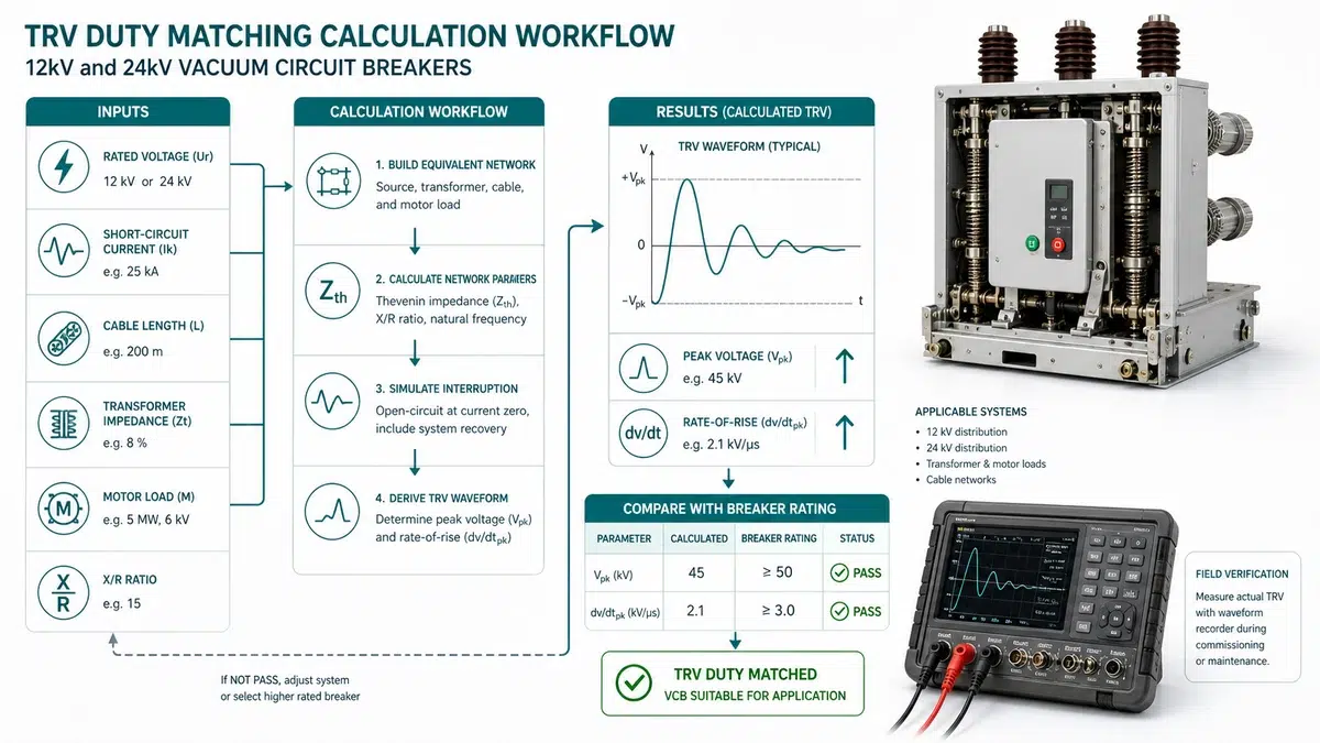
Field deployments rarely match the clean topology assumed in type-test laboratories. The matrix below organises the most common industrial feeder topologies by voltage class and identifies where each breaker is comfortable, marginal, or at risk.
| Feeder Topology | Dominant TRV Stress | 12kV VCB Performance | 24kV VCB Performance | Critical Variable |
|---|---|---|---|---|
| Radial cable feeder (100% cable) | Low RRRV, high capacitance damps TRV | Comfortable margin | Often over-specified unless fault level is high | Cable length |
| Overhead line feeder (100% OHL) | High RRRV, low shunt capacitance | Marginal on long rural feeders | Standard margin; preferred above 15kV | Line length |
| Mixed cable-OHL feeder | TRV shape distortion at transition point | Requires site-specific calculation | Better tolerance to junction reflections | Length ratio cable-to-OHL |
| MV/LV transformer feeder (delta-star, unearthed primary) | TLF condition; high initial RRRV | High risk at T100 without surge capacitor | Adequate if fault level <= 63% rated; TLF still requires review | Transformer kVA, leakage inductance |
| Motor feeder (large HV motor, direct-on-line) | Current chopping, virtual chopping | Chopping overvoltage risk; surge arresters mandatory | Same chopping risk; arrester coordination simpler | Motor inductance, parallel motor count |
| Power factor correction feeder (capacitor bank) | Capacitive current interruption | Reignition risk if bank is ungrounded | Reduced reignition risk due to wider contact gap | Bank size, earthing method |
| Industrial cogeneration tie (synchronous generator) | Out-of-phase switching | Requires explicit out-of-phase rating check | Better voltage margin; Uc still approaches 2 pu | Phase angle at interruption |
12kV VCBs perform well in high-capacitance cable-only feeders where fault levels are moderate (<= 25 kA), but they become risky on transformer-limited fault conditions without surge capacitors and on long OHL sections with low shunt capacitance. 24kV VCBs are preferred in mixed-topology feeders, cogeneration tie applications, and locations where voltage could be elevated by capacitor-bank switching or out-of-phase synchronising events. Over-specifying at 24kV for a nominal 12kV system without recalculating arrester and cable insulation coordination creates a protection gap rather than a safety margin.
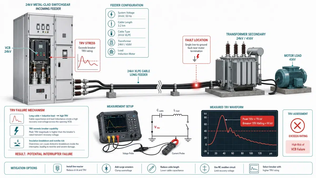
This field example shows why nameplate short-circuit current alone is not enough. A 24kV motor feeder was fitted with a 25 kA breaker that looked acceptable on current rating, but measured recovery voltage after interruption reached 58.4 kV with a 4.8 kV/micro-s RRRV. The service example pointed to a TRV mismatch, not a weak operating mechanism or a contact-resistance problem. The corrective decision was to combine an RC snubber with a breaker type-tested for the higher first-pole-to-clear factor.
A 24kV VCB on a cable feeder serving a large induction motor drive station exhibited repeated contact erosion and two restrike events during fault interruption. The breaker had been selected on rated short-circuit breaking current (25 kA) alone with no TRV duty check; the feeder consisted of approximately 800 m of XLPE cable with no capacitive compensation, and contact erosion exceeded 50% of allowable depth at 340 operations.
| Parameter | Measured Value | IEC 62271-100 T100s Reference | Status |
|---|---|---|---|
| Peak TRV (Uc) | 58.4 kV | 54.0 kV (24kV, T100s) | Exceeds standard |
| Rate of rise (RRRV) | 4.8 kV/micro-s | 2.0 kV/micro-s (T100s) | Exceeds standard – more than 2x |
| Time to peak (t3) | 36 micro-s | 52 micro-s | Faster than reference |
| First-pole-to-clear factor | 1.5 | 1.3 (assumed effectively earthed) | Higher than assumed |
Factor 1 – Transformer earthing misclassification. The measured X0/X1 ratio of 3.8 placed the system in the non-effectively earthed category, raising kpp from 1.3 to 1.5; the installed breaker held a T100s rating only and had not been type-tested to the 1.5 factor variant.
Factor 2 – Short cable run with minimal capacitive damping. The 800 m XLPE cable provided insufficient distributed capacitance to suppress the RRRV. Cable feeders longer than approximately 2,000 m in this voltage class typically reduce RRRV into a manageable range; below that threshold, transformer terminal capacitance dominates and the TRV oscillation is fast and underdamped.
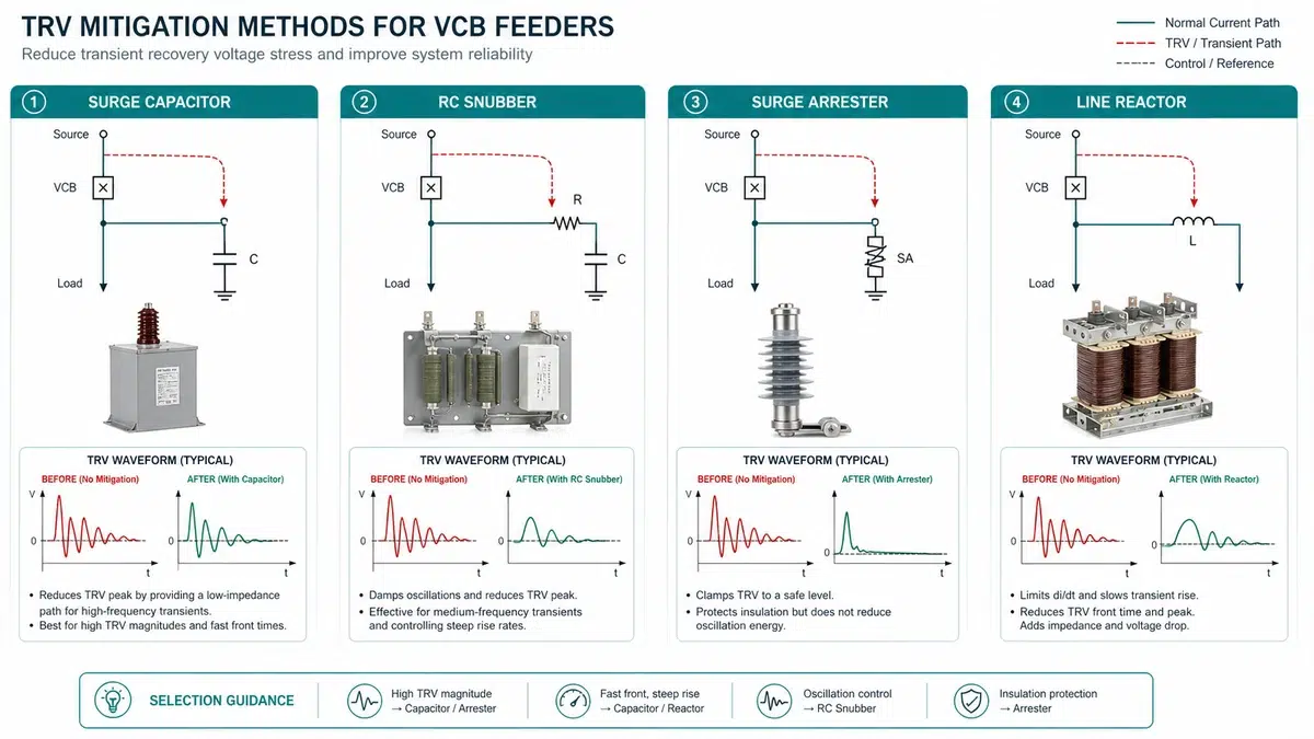
When TRV duty matching confirms that a circuit’s inherent TRV envelope exceeds the breaker’s rated capability, suppression methods must be evaluated. Characterise the problem first: a peak amplitude violation calls for a different fix than an RRRV violation.
| Problem Type | Primary Indicator | Preferred Mitigation Class |
|---|---|---|
| Peak amplitude excess | Uc > rated TRV peak | Surge capacitor, RC snubber |
| RRRV excess | dU/dt > rated limit | RC snubber, surge capacitor in series with resistance |
| Both amplitude and rate | Both thresholds crossed | RC snubber with optimized component sizing |
| Short-line fault TRV | Overhead sections <= 1 km from breaker | Line-side inductance addition, capacitor bank |
| Transformer-limited TRV | Low-impedance transformer on source side | Source-side RC snubber, reactor insertion |
Surge capacitors (0.1-0.5 micro-F per phase) connected line-to-earth slow the initial rate of voltage rise by increasing effective shunt capacitance. Do not exceed 1 micro-F per phase without re-evaluating making current duty on closing; in cable-fed systems with already-high distributed capacitance, the benefit diminishes while energisation charging current increases.
RC snubbers place a resistor in series with the capacitor, damping the oscillatory TRV waveform and reducing first-peak overshoot. They address both RRRV and peak amplitude simultaneously and are the preferred solution when the TRV waveform is oscillatory. Size the resistor for total energy across an O-CO-CO sequence per IEC 62271-100, not a single operation.
| System Voltage | Capacitance Range | Resistance Range | Damping Ratio Target |
|---|---|---|---|
| 12kV | 0.05-0.25 micro-F | 30-150 ohm | 0.3-0.7 |
| 24kV | 0.05-0.20 micro-F | 50-200 ohm | 0.3-0.7 |
| Mitigation Method | Reduces RRRV | Reduces Peak | Addresses SLF | Installation Complexity | Main Risk |
|---|---|---|---|---|---|
| Surge capacitor | Yes | Marginal | No | Low | Overcurrent on close |
| RC snubber | Yes | Yes | No | Medium | Resistor energy rating |
| Series reactor | Yes | Indirect | Partial | High | Load voltage drop |
| Surge arrester | No | No (within TRV range) | No | Low | Misapplication |
Purchasing a vacuum circuit breaker without anchoring the specification to the actual TRV envelope of your network is one of the most common root causes of nuisance re-ignition, vacuum interrupter failure, and accelerated contact erosion in industrial 12kV and 24kV systems.
Start with the same electrical data used for protection coordination: rated voltage, maximum fault level, X0/X1 earthing ratio, cable length, transformer leakage impedance, motor contribution, and any overhead-line section within the first kilometre from the breaker. If the project has not selected a breaker family yet, use the XBRELE vacuum circuit breaker overview to align voltage class, mechanism type, and installation format before requesting type-test documents.
For incoming inspection and commissioning, connect the TRV requirement to the VCB FAT/SAT acceptance test checklist so that the procurement promise is converted into testable site records.
TRV duty matching is the process of comparing the transient recovery voltage that a network will impose across a vacuum circuit breaker’s open contacts against the TRV withstand capability declared in the breaker’s type test certificate. A breaker that passes its rated symmetrical short-circuit current test can still fail in service if the actual RRRV or peak TRV exceeds the tested envelope.
Transformer-limited fault conditions, where the breaker clears a fault at or near the secondary terminals of a step-down transformer with no intermediate shunt capacitance, produce the steepest RRRV because transformer leakage inductance alone governs the recovery oscillation. RRRV values exceeding 20 kV/micro-s are documented in this topology at 24kV.
The most effective method is to install a surge capacitor (0.1-0.5 micro-F per phase) at the transformer primary terminals or the load-side busbar of the breaker, increasing shunt capacitance at the circuit node and slowing the initial rate of voltage recovery. Where the TRV waveform is oscillatory as well as steep, an RC snubber (capacitor in series with a damping resistor of 30-200 ohm depending on voltage class) addresses both RRRV and peak amplitude simultaneously.
As a minimum, the supplier must provide a third-party type test certificate (from KEMA, CESI, PEHLA, or an equivalent accredited laboratory) that explicitly covers all four IEC 62271-100 test duties – T10, T30, T60, and T100 – at the exact rated voltage of the quoted product, traceable to the specific vacuum interrupter design in the quoted unit. For feeders with overhead line sections, an SLF test report is also required.
Earthing classification directly sets the first-pole-to-clear factor (kpp) used to calculate the prospective peak TRV. For effectively earthed systems (X0/X1 ratio < 3.0), kpp = 1.3 is standard; for non-effectively earthed, isolated, or resonant-earthed neutral systems, kpp = 1.5 applies, increasing the prospective peak TRV by approximately 15% and requiring a breaker type-tested to the corresponding higher envelope.
Below approximately 1,500 m of XLPE cable at 12kV, distributed capacitance is insufficient to suppress the RRRV driven by the source transformer’s leakage inductance, and RRRV can exceed the T100s reference limit of 2-3 kV/micro-s. For cable runs shorter than 500 m, short-line fault conditions must also be checked because travelling wave reflections arrive back at the breaker terminal within the first few microseconds of recovery, creating a steep initial TRV segment.
XBRELE provides technical support for TRV duty matching on 12kV and 24kV industrial feeders, including application review, simulation support, and supply of type-tested vacuum circuit breakers with full IEC 62271-100 documentation. Contact the XBRELE engineering team to discuss your feeder parameters, or browse the medium voltage VCB product range to review rated TRV envelopes by product family.