Need Full Specifications?
Download our 2025 Product Catalog for detailed drawings and technical parameters of all switchgear components.
Get CatalogDownload our 2025 Product Catalog for detailed drawings and technical parameters of all switchgear components.
Get CatalogDownload our 2025 Product Catalog for detailed drawings and technical parameters of all switchgear components.
Get Catalog
Plan an air-to-vacuum contactor retrofit with checks for fit, ratings, control wiring, surge protection, and commissioning.
The transition from air contactors to vacuum contactors represents one of the most significant upgrades available for medium-voltage motor control centers and switchgear installations. After spending nearly two decades commissioning and troubleshooting these retrofits across petrochemical plants, water treatment facilities, and manufacturing operations, I can confidently say that this upgrade delivers substantial operational benefits—but only when executed with meticulous attention to compatibility, control circuit modifications, and proper commissioning procedures.
Air contactors, while reliable workhorses in their time, present increasing challenges for modern facilities. Their higher maintenance requirements, larger physical footprints, and limited interrupting capacities make them candidates for replacement, particularly in installations dating from the 1970s through 1990s. Vacuum contactors offer superior arc interruption, dramatically reduced maintenance intervals, and enhanced operational safety.
This article provides a detailed technical roadmap for engineers, maintenance professionals, and project managers undertaking air-to-vacuum contactor retrofits. Drawing from real-world project experience and established industry practices, we’ll examine every critical aspect of this upgrade process.
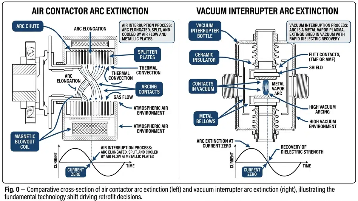
Air contactors rely on arc chutes with multiple splitter plates to cool and lengthen the arc during contact separation. The arc extinguishes when the current passes through zero, but the process generates significant ionized gases and contact erosion. This mechanism limits air contactors to approximately 50,000 operations before requiring major maintenance.
Vacuum contactors operate on an entirely different principle. The contacts separate within a sealed vacuum interrupter (typically 10⁻⁶ to 10⁻⁸ torr), where the absence of ionizing medium causes rapid arc extinction—often within half a cycle. This results in contact life extending to 1-2 million mechanical operations and 100,000+ electrical operations at rated current.
| Parameter | Air Contactor | Vacuum Contactor |
|---|---|---|
| Arc duration | 8-15 ms | 2-4 ms |
| Contact erosion per operation | 0.1-0.3 mm³ | 0.001-0.01 mm³ |
| Dielectric recovery | Gradual | Near-instantaneous |
| Chopping current | 5-15 A | 3-8 A (modern designs) |
| Restrike probability | Low | Very low |
The shorter arc duration of vacuum contactors means lower let-through energy during interruption, but it also creates faster current chopping that can generate voltage transients—a critical consideration we’ll address in the control modifications section.
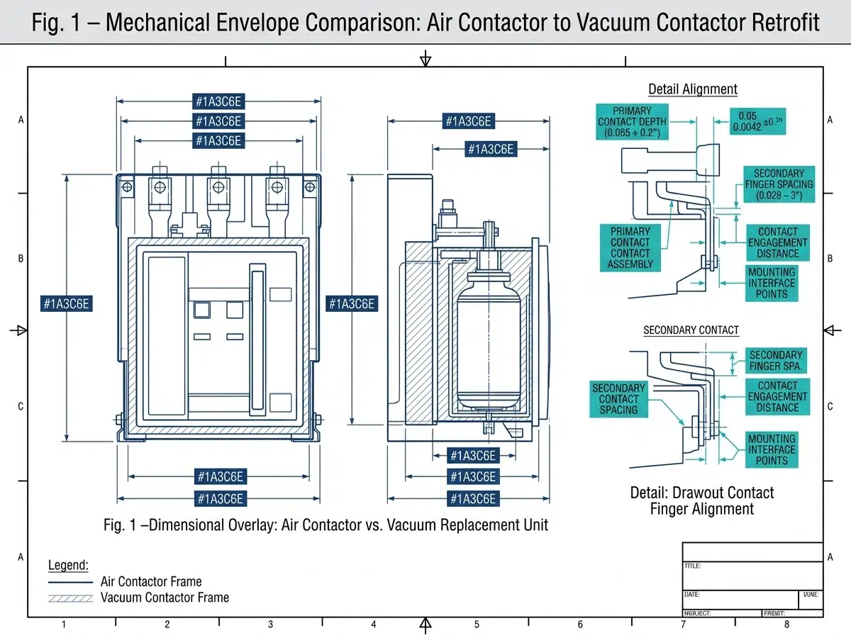
Before ordering replacement equipment, conduct a thorough dimensional survey of the existing installation. Modern vacuum contactors are typically more compact than their air counterparts, but mounting configurations vary significantly between manufacturers.
Critical measurements include:
– Vertical clearance: Vacuum contactors often have different height requirements due to integral surge suppression or electronic coil modules
– Mounting hole patterns: Rarely identical; adapter plates are usually necessary
– Phase spacing: Must match existing bus configurations or require bus modifications
– Door clearance: Some vacuum contactors have front-projecting operating mechanisms
During a recent retrofit at a Gulf Coast refinery, we discovered that the replacement vacuum contactors required 3 inches of additional depth clearance due to rear-mounted auxiliary contact blocks. This necessitated relocating terminal blocks and extending control wiring—a scope change that added two days to the project schedule.
Rating compatibility extends beyond simple voltage and current matching:
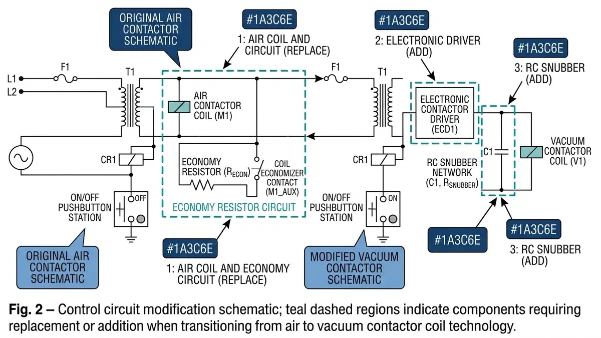
Modern vacuum contactors frequently incorporate electronic control modules that differ fundamentally from the electromagnetic coils in air contactors. These modules typically require:
– Clean DC or AC power supplies
– Specific minimum pulse widths for reliable operation
– Different auxiliary contact timing sequences
– Compatibility verification with existing PLC or relay logic
Traditional air contactor coils draw significant inrush current (often 8-10 times sealed current) followed by a steady holding current. The coil itself provides inherent resistance to control circuit variations. Vacuum contactor electronic coil drives operate differently:
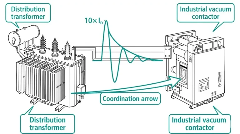
When retrofitting, verify that control power sources can provide adequate current during simultaneous operation of multiple contactors—a situation common during motor bus transfers.
Air contactors typically have dedicated auxiliary contact blocks with fixed timing relative to main contact operation. Vacuum contactors offer greater flexibility but require careful configuration:
Pre-energization contacts must close before the main vacuum contacts to allow surge protection circuits to arm. Seal-in contacts may require timing adjustments to account for different operating times. Status feedback contacts need verification of adequate current-carrying capacity for connected loads.
I recommend creating a detailed auxiliary contact mapping document comparing existing functions with replacement contactor capabilities before beginning physical installation.
The fast switching characteristics of vacuum contactors can generate voltage transients when interrupting motor currents. These transients, caused by current chopping and virtual current chopping phenomena, can stress motor insulation and cause control system interference.
Required surge protection typically includes:
– RC snubbers (resistor-capacitor networks) across each phase
– Metal oxide varistors (MOVs) rated for system voltage and energy absorption requirements
– Surge capacitors for motors with upgraded insulation systems
For motors built before the late 1990s, which may have lower basic impulse insulation levels (BIL), surge protection is mandatory. Calculate energy requirements based on motor inductance and chopping current levels.
De-energize and lock out/tag out all power sources, including control power and potential transformer circuits. Verify zero energy state using properly rated test equipment.
Document all existing wiring connections with photographs and detailed labeling before disconnection. This documentation proves invaluable during commissioning troubleshooting and creates permanent records for facility documentation systems.
Remove arc chute assemblies first, followed by auxiliary devices, then main contactor withdrawal. Inspect cell bushings and bus stabs for signs of overheating or damage that should be addressed before installing new equipment.
Most retrofits require custom adapter plates to match mounting hole patterns. These plates must:
– Maintain proper phase spacing and creepage distances
– Provide adequate mechanical support for operating forces
– Allow proper alignment with existing bus stabs
– Accommodate differences in operating mechanism location
Vacuum contactor bus stabs may differ from air contactor designs. Verify proper engagement depth and contact pressure. Apply appropriate contact lubricant per manufacturer specifications. Torque all connections to specified values and document readings.
Create a comprehensive wiring schedule comparing existing terminal designations with replacement contactor requirements. Key areas requiring attention include:
Differences in operating times and auxiliary contact behavior may require logic timing modifications:
Verify that existing motor protection settings remain appropriate. Some vacuum contactors include integral current transformers for electronic overload protection, potentially allowing retirement of discrete CT and relay assemblies.
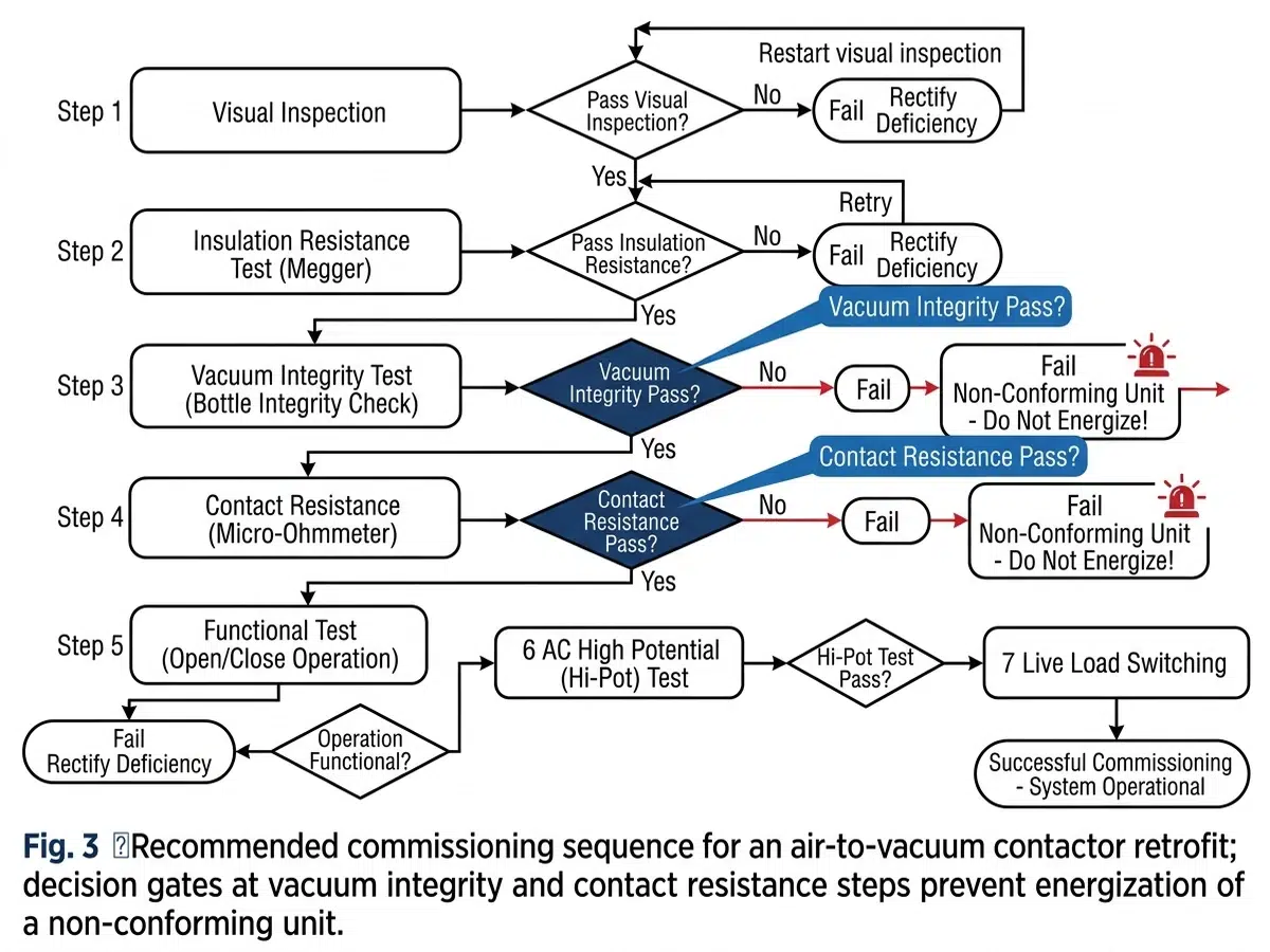
Before applying any power, complete these verification steps:
Energize control power only and verify:
– Proper coil pickup and dropout voltages
– Auxiliary contact sequence timing
– Interlock functionality with associated equipment
– PLC/DCS feedback signal integrity
– Local and remote control functionality
After successful control circuit testing, proceed to load testing:
Document all test results and compare against manufacturer specifications and baseline requirements.
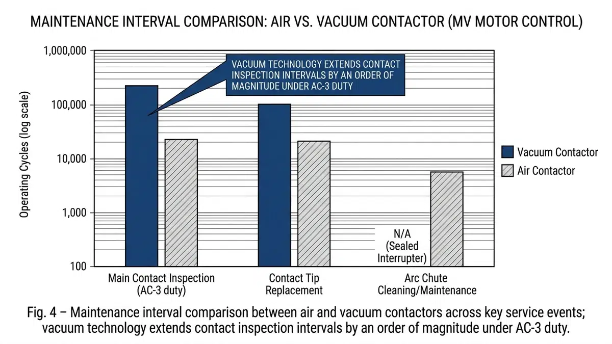
Vacuum contactors dramatically reduce maintenance requirements compared to air contactors:
| Maintenance Activity | Air Contactor | Vacuum Contactor |
|---|---|---|
| Contact inspection | 6-12 months | 3-5 years |
| Arc chute cleaning | 6-12 months | Not applicable |
| Mechanical lubrication | Annually | 2-5 years |
| Complete overhaul | 25,000-50,000 operations | 500,000+ operations |
Despite reduced maintenance, certain parameters require ongoing monitoring:
– Operations counter: Track operations against rated life
– Contact erosion indicators: Many modern vacuum contactors include wear indicators
– Vacuum integrity: Periodic testing if the unit lacks integral monitoring
– Auxiliary contact condition: These wear faster than main vacuum contacts
Maintain appropriate spare parts inventory:
– Complete replacement vacuum interrupters
– Electronic coil drive modules
– Auxiliary contact blocks
– Surge protection components (RC snubbers, MOVs)
Based on projects I’ve managed across various industries, ROI typically occurs within 2-4 years. The calculation includes reduced maintenance labor (typically 4-8 hours per contactor annually), eliminated arc chute replacement costs ($500-1,500 per unit), reduced downtime for maintenance, and improved motor protection reducing motor repair costs. For continuously operating facilities with multiple retrofits, payback often occurs within 18 months.
Direct replacement is rarely possible without modifications. While vacuum contactors are generally smaller, differences in mounting configurations, control circuit requirements, and bus stab arrangements typically require adapter plates and wiring modifications. However, manufacturers offer retrofit kits specifically designed to simplify installation in common legacy motor control center designs. Always verify compatibility with both the contactor manufacturer and original MCC manufacturer.
Retrofit installations often require more extensive surge protection because motors in existing facilities may have older insulation systems with lower surge withstand capabilities. Motors manufactured before 1995, particularly those wound prior to the adoption of inverter-duty insulation standards, are more susceptible to vacuum contactor switching transients. I recommend surge protection for any motor where insulation condition or age is uncertain, regardless of theoretical BIL ratings.
Maintenance personnel should receive manufacturer-specific training covering vacuum interrupter handling (critical—never attempt to disassemble vacuum bottles), electronic coil drive diagnostics and replacement, proper testing procedures for vacuum integrity, and safety considerations specific to the installed equipment. The investment in training prevents costly errors and ensures personnel safety around medium-voltage equipment.
Several methods exist for vacuum integrity verification: high-potential testing (withstand indicates adequate vacuum), magnetron testing (specialized equipment measures internal pressure), X-ray observation (shows internal arc erosion), and manufacturer-integral indicators (some designs include lifetime indicators). For critical applications, I recommend establishing a baseline with magnetron testing at commissioning, followed by periodic verification at 5-year intervals.
Comprehensive documentation should include pre-retrofit equipment condition assessment and photographs, detailed wiring schedules comparing existing and new configurations, adapter plate drawings with dimensions and torque specifications, commissioning test results (insulation resistance, contact resistance, timing, surge measurements), updated single-line and schematic drawings reflecting as-built conditions, and maintenance procedure revisions for vacuum contactor requirements. This documentation supports future maintenance, satisfies regulatory requirements, and facilitates troubleshooting.
Certain applications warrant careful evaluation before proceeding: extremely high-frequency switching applications (some air contactors handle specific inching/plugging scenarios better), installations where system fault current exceeds available vacuum contactor ratings, situations where control system integration presents insurmountable compatibility challenges, and facilities planning near-term complete motor control center replacement where retrofit economics become unfavorable.
Air contactor to vacuum contactor retrofits deliver measurable benefits in reliability, maintenance reduction, and operational safety when properly executed. Success depends on thorough pre-retrofit assessment addressing physical, electrical, and control system compatibility.
Critical success factors include:
Comprehensive compatibility evaluation before equipment procurement, including physical dimensions, electrical ratings, and control circuit requirements
Proper surge protection design based on motor age, insulation condition, and switching duty requirements
Detailed wiring documentation created during removal and used to guide reinstallation
Systematic commissioning following a structured protocol that verifies mechanical, electrical, and protection system functionality
Updated maintenance procedures that leverage vacuum contactor advantages while maintaining appropriate monitoring intervals
Personnel training ensuring maintenance staff understand the different characteristics and requirements of vacuum technology
The investment in proper planning and execution returns dividends throughout the equipment lifecycle. Facilities that approach these retrofits systematically report significant reductions in unplanned downtime, maintenance costs, and safety incidents.
For additional technical guidance on medium-voltage equipment retrofits, consider reviewing the IEEE C37.09 standard for AC high-voltage circuit breaker testing, which provides relevant protocols applicable to vacuum contactor commissioning. Internal resources on [motor protection coordination], [medium-voltage switchgear maintenance], [surge protection system design], and [vacuum interrupter testing procedures] provide supplementary information supporting successful retrofit projects.