Need Full Specifications?
Download our 2025 Product Catalog for detailed drawings and technical parameters of all switchgear components.
Get Catalog
Download our 2025 Product Catalog for detailed drawings and technical parameters of all switchgear components.
Get Catalog Download our 2025 Product Catalog for detailed drawings and technical parameters of all switchgear components.
Get Catalog
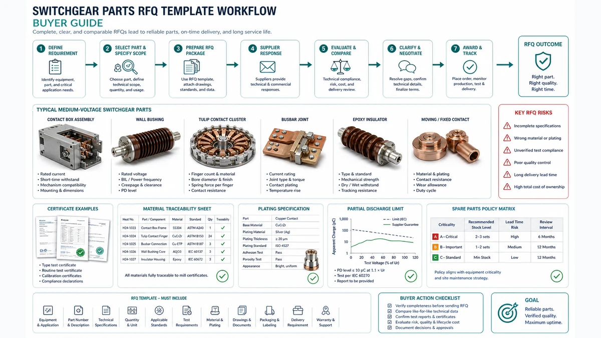
Procuring replacement or spare switchgear components without a structured request-for-quotation document is one of the most reliable ways to receive non-conforming parts, miss lead times, or accept material substitutions that compromise dielectric integrity. This guide assembles every element a procurement or engineering team needs to build a defensible switchgear parts RFQ template – from material and partial discharge clauses through plating specifications, traceability requirements, spare parts policy, supplier matching, and bid validation.
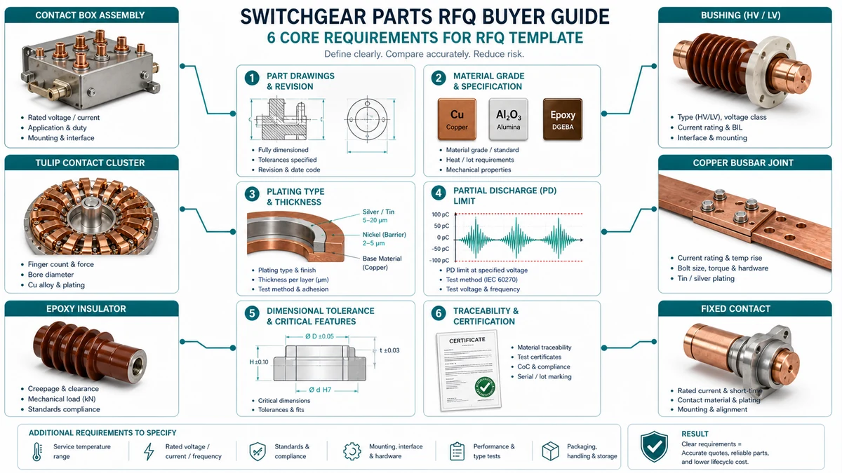
A switchgear parts RFQ template is a structured document that defines the technical, commercial, and compliance requirements a buyer communicates to suppliers before receiving a quotation. Without a complete template, suppliers quote incompatible material grades, omit test certificates, or misinterpret dielectric limits.
A switchgear parts RFQ template that omits precise material grades and PD thresholds forces suppliers to quote against assumptions, producing mismatched components, hidden substitutions, and post-delivery disputes.
Current-carrying conductors – Specify alloy designation, temper, and minimum conductivity together. Stating “copper” is insufficient; C11000 (electrolytic tough pitch, 100% IACS minimum) and C10200 (oxygen-free, 99.95% IACS minimum) behave differently under cyclic thermal loading. For busbars rated above 1,600 A, CuCrZr (CW106C) reduces creep at joint interfaces.
Insulating structures – Cast epoxy, SMC, and DMC all appear in medium-voltage switchgear but are not interchangeable:
| Material | CTI (IEC 60112) | Temp. Class | Where It Wins | Where It Becomes Risky |
|---|---|---|---|---|
| Cast epoxy (cycloaliphatic) | >= 600 (Class I) | 130 deg C (B) | Dry indoor, HV insulator applications | Humid or polluted environments without hydrophobic additive |
| SMC (Class F filled) | 400-600 | 155 deg C (F) | High-volume molded parts, moderate pollution | Porosity risk in thick sections |
| DMC / BMC | 250-400 | 130 deg C (B) | Low-cost mechanical housings | Avoid for live-part insulation above 12 kV |
| PTFE / PEEK | > 600 | 260 deg C (C) | High-temperature or chemical-exposure zones | Cost-prohibitive at scale |
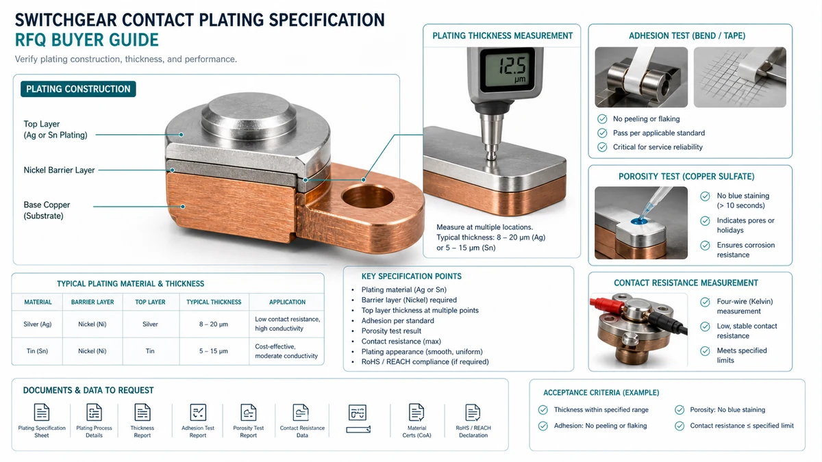
Plating failures on switchgear contact parts rarely appear at incoming inspection – they show up later as elevated contact resistance, micro-arcing, or thermal runaway. The root cause is usually an RFQ clause that stated a finish type without specifying thickness, substrate preparation, adhesion requirement, or porosity limit.
| Plating System | Wins | Becomes Risky |
|---|---|---|
| Silver over nickel barrier (rack) | Low contact resistance, high switching cycles | Silver migration in humid DC environments |
| Silver over copper (no barrier) | Lower cost, acceptable for low-cycle breakers | Copper diffusion above 70 deg C; delamination under fretting |
| Tin over nickel | Good corrosion resistance | Tin whisker growth; restricted under RoHS |
| Hard silver (alloyed Ag) | Better wear on sliding contacts | Slightly higher contact resistance than pure Ag |
| Gold flash over nickel | Excellent for low-current signal contacts | Uneconomical and soft for power contacts |
Field 1 – Base metal and surface condition: State substrate alloy and required pre-plate surface finish. Example: Substrate: C11000. Pre-plate surface finish: Ra <= 0.8 micro-m. No burrs, pits, or porosity visible at 10x magnification prior to activation.
Field 2 – Barrier layer: Nickel barrier: Required. Electroplated per ASTM B689. Minimum thickness 2.5 micro-m, maximum 5.0 micro-m.
| Lot Size | Minimum Sample Size | Critical Defect AQL | Major Defect AQL |
|---|---|---|---|
| <= 50 pcs | 100% inspection | Zero accept | Zero accept |
| 51-200 pcs | 13 pcs (ANSI/ASQ Z1.4, Level II) | AQL 0.065 | AQL 0.65 |
| 201-1,200 pcs | 32 pcs | AQL 0.065 | AQL 0.65 |
| > 1,200 pcs | 80 pcs | AQL 0.065 | AQL 0.65 |
Traceability failures are a leading cause of counterfeit parts entering switchgear assemblies. A part lacking a documented chain of custody from raw material to delivery cannot be verified, recalled systematically, or used to support root-cause analysis after a failure event.
| Symptom | First Test | Likely Root Cause | Next Action |
|---|---|---|---|
| CoC references grade only, no heat number | Request lot-specific MTR | Material traceability not maintained at lot level | Disqualify or require 100% lot re-certification |
| Test records undated or unsigned | Request calibration certificates | Records generated retrospectively | Place supplier on probation; conduct audit |
| Part marking is label-only on contact surface | Request sample with permanent marking | Supplier lacks etching or stamping capability | Require alternative permanent marking method |
| Calibration traceability not stated on test record | Request NIST/PTB/NPL declaration | Informal calibration regime | Suspend receiving acceptance until clarified |
| No shelf-life data for elastomeric components | Request material datasheet | Component not recognized as time-sensitive | Add shelf-life clause to existing PO; re-inspect stock |
| Instrument / Source | Purpose | Acceptance Reference |
|---|---|---|
| Contact resistance tester (four-wire, micro-ohm range) | Verify electrical integrity of plated contacts | IEC 60352; OEM manual |
| Insulation resistance tester (500 V-5 kV DC) | Screen for moisture ingress or contamination | IEC 60664-1; project specification |
| Partial discharge analyzer (IEC 60270-compliant) | Confirm dielectric integrity of insulation components | IEC 62271-1; OEM type test record |
| Dimensional CMM or calibrated calipers | Verify dimensional compliance to drawing revision | First article inspection report |
| X-ray fluorescence (XRF) analyzer | Confirm plating alloy and thickness | ASTM B567; ASTM B499 |
| EN 10204 Type 3.1 MTR | Confirm raw material composition and properties | EN 10204; purchase order traceability clause |
| OEM parts manual or service documentation | Cross-reference part numbers and revision levels | OEM manual (current revision) |
| AS5553 counterfeit prevention program records | Verify anti-counterfeit controls | AS5553 or equivalent buyer policy |
Layer 1 – Material Origin: Suppliers must provide mill certificates traceable to the heat or lot number. Accept nothing that references only a material grade without a specific heat number.
Layer 2 – Manufacturing Process Records: Required documents include works order with date and operator identification, plating bath records (chemistry, temperature, current density, thickness), heat treatment records where applicable, and dimensional inspection reports tied to the same job number.
| Test Type | Minimum Record Content | Acceptable Format |
|---|---|---|
| Dimensional inspection | Drawing revision, measurement values, pass/fail | First article inspection (FAI) report |
| Dielectric / hi-pot | Applied voltage, duration, leakage current | Test certificate with calibrated equipment ID |
| Contact resistance | Measured micro-ohm value, test current, ambient temperature | Tabulated with part serial or lot number |
| Partial discharge | Inception voltage, extinction voltage, pC level | IEC 60270-compliant report |
| Visual / surface inspection | Inspector ID, magnification used, rejection criteria | Per IEC 60068 or equivalent |
| Supplier Category | Traceability Strength | Typical Gap | Risk Level |
|---|---|---|---|
| OEM-authorized distributor | Layers 1-3 strong | Layer 4 marking sometimes delegated | Low-Medium |
| Independent aftermarket manufacturer | Layers 2-3 variable | Layer 1 heat traceability often missing | Medium-High |
| Spot-market broker | Layer 1 only (if at all) | Layers 2-4 typically absent | High |
| OEM direct | All four layers standard | Retention period may need negotiation | Low |
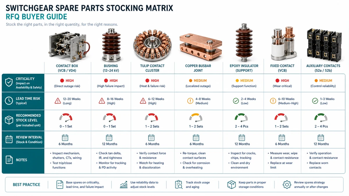
A spare parts policy written into the RFQ template before vendor selection prevents the most common post-commissioning failure: discovering that a critical vacuum interrupter or trip coil carries a 16-week lead time only after an unplanned outage has started.
| Consequence if Failed | Lead Time <= 4 weeks | Lead Time 5-16 weeks | Lead Time > 16 weeks |
|---|---|---|---|
| Process-critical (forced outage) | Carry 1 unit on-site | Carry 2 units on-site | Carry 2 units + frame agreement |
| Maintenance-critical (derated operation) | Carry 0, order at PM | Carry 1 unit on-site | Carry 1 unit + quarterly replenishment trigger |
| Non-critical (cosmetic, redundant path) | Carry 0 | Carry 0 | Carry 0 |
Sending a well-structured RFQ to the wrong supplier pool produces quotes that cannot be compared, lead times that will be missed, and parts that fail qualification at incoming inspection.
Voltage class: Medium-voltage parts (1 kV-36 kV) demand PD testing and dielectric traceability that most low-voltage distributors cannot support. If the RFQ mixes voltage classes, segment it into separate packages.
Environment category:
| Tier | Conditions | Minimum Supplier Requirement |
|---|---|---|
| Standard | Indoor, controlled humidity, low pollution | Basic dimensional and material certs |
| Harsh | Coastal, industrial atmosphere, moderate vibration | Salt spray test data, plating traceability |
| Severe | High altitude, extreme temperature cycling, offshore | Full material traceability, third-party environmental test reports, field reference list |
| Evaluation Criterion | Suggested Weight |
|---|---|
| Technical compliance (material, PD, plating) | 30% |
| Documentation completeness | 20% |
| Lead time credibility (backed by production data) | 20% |
| Unit price and total landed cost | 15% |
| Quality system and traceability | 10% |
| Spare parts availability commitment | 5% |
A returned RFQ response is not automatically a valid bid. Apply the checklist below before price comparison begins.
| Check Item | Mandatory? | Pass Criteria | Common Fail Pattern |
|---|---|---|---|
| Base material alloy specified (UNS or equivalent) | Yes | Exact alloy grade stated; no generic terms such as “copper alloy” | Supplier lists material family only |
| Material conforms to RFQ-specified grade | Yes | Stated alloy matches RFQ or approved equivalent justified in writing | Substitution offered without justification |
| Mill or foundry identified | Yes | Named source; “approved supplier” is not acceptable | Anonymous supply chain reference |
| RoHS / REACH compliance confirmed | Yes (if required) | Written declaration or certificate reference provided | Absence of declaration for EU-destined equipment |
| Check Item | Mandatory? | Pass Criteria | Common Fail Pattern |
|---|---|---|---|
| Acceptance PD level stated in pC at specified voltage | Yes | Numeric pC value at defined test voltage | Vague language; no test voltage reference |
| Test standard cited (IEC 60270 or equivalent) | Yes | Standard number included | Standard omitted or superseded version cited |
| Sample test reports available | Yes | Offered or attached; lot-based reports preferred | “Available on request” without commitment |
| Insulation material brand or grade identified | Yes | Named product; generic “epoxy” is insufficient | Material unspecified |
| Check Item | Mandatory? | Pass Criteria | Common Fail Pattern |
|---|---|---|---|
| Plating type and thickness stated | Yes | Plating chemistry and minimum thickness in micro-m | Thickness range too broad or absent |
| Plating standard referenced | Yes | Standard number cited (e.g., ASTM B545) | No standard cited; proprietary process only |
| Barrier layer declared where applicable | Conditional | Stated where nickel strike or similar is used | Omitted for silver-plated copper |
| RoHS compliance of plating materials confirmed | Yes (if required) | Written statement or certificate | Absence of declaration |
| Shelf-life limitation for plated parts stated | Yes | Months or years from date of manufacture | No shelf-life stated |
| Check Item | Mandatory? | Pass Criteria | Common Fail Pattern |
|---|---|---|---|
| Heat number or lot number traceable to material certificate | Yes | Specific heat or lot number on CoC and MTR | CoC references grade only |
| EN 10204 certificate type confirmed | Yes | Type 3.1 or 3.2 as specified; Type 2.2 not acceptable for primary current path | Downgraded certificate type offered |
| Test equipment calibration traceability stated | Yes | National measurement standard referenced | Calibration certificate absent or expired |
| Permanent part marking confirmed | Yes | Method stated (laser, electrochemical, stamp); labels alone not accepted | Label-only marking offered |
| Record retention period stated | Yes | Meets or exceeds buyer-specified period | Retention period unstated or below requirement |
| Check Item | Mandatory? | Pass Criteria | Common Fail Pattern |
|---|---|---|---|
| Ex-works lead time stated per SKU | Yes | Specific weeks; not a range exceeding +/-2 weeks | Vague “standard lead time” without number |
| MOQ and packaging quantity confirmed | Yes | Stated per line item | MOQ not declared; discovered post-order |
| Obsolescence status declared | Yes | Active, end-of-life, or last-time-buy status stated | No declaration; assumed active |
| Frame agreement or reserved capacity offered | Conditional | Stated where process-critical classification applies | Not addressed for long-lead critical parts |
| Shelf-life and storage conditions stated per SKU | Yes | Specific temperature range, humidity limit, and expiry date format | Absent for elastomeric or insulation components |
Use these XBRELE references to connect the field decision to the correct product, test, and procurement workflow: XBRELE product page, XBRELE vacuum circuit breaker range, VCB ratings guide, VCB FAT/SAT acceptance checklist.
For external method context, compare the site procedure with the public IEEE C37.09 standards page and then apply the exact OEM manual and project specification for the supplied equipment.
Field example: during a service inspection, one phase measured outside its commissioning baseline while the other two phases remained stable. The team repeated the measurement with verified leads, checked timing and contact travel, and used the measured divergence to separate a contact-pressure problem from a generic surface-cleaning issue.
A switchgear parts RFQ template should require material grade, drawing revision, voltage class, rated current path, partial discharge limit, plating type and thickness, test standard, traceability certificate type, spare policy, packaging requirement, and delivery lead time. Missing any of these fields turns supplier comparison into a price-only exercise instead of a technical qualification.
For many solid-insulation assemblies in 12-36 kV switchgear, buyers commonly specify <= 5 pC at the defined test voltage, measured per IEC 60270. The exact value must follow the project specification, component type, insulation system, and end-user standard.
Silver plating for electrical contacts is commonly specified with ASTM B700 or an equivalent recognized plating standard. The RFQ should state minimum thickness, barrier layer requirements, adhesion test, porosity acceptance, and whether rack plating or barrel plating is acceptable for the contact geometry.
For primary current path components, specify EN 10204 Type 3.1 or an equivalent certificate that links material grade, heat number, test result, and production lot. A generic certificate of conformity is not enough when the part affects temperature rise, contact resistance, insulation coordination, or long-term spare interchangeability.
Use a consequence and lead-time matrix. A process-critical contact box, bushing, interlock, or tulip contact with an 8-14 week lead time may justify two units on site plus a supplier frame agreement.
PDIV is the partial discharge inception voltage where discharge first appears during a rising voltage test. PDEV is the partial discharge extinction voltage where discharge stops during a falling voltage test.